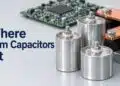

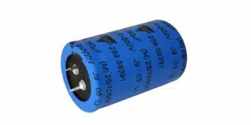


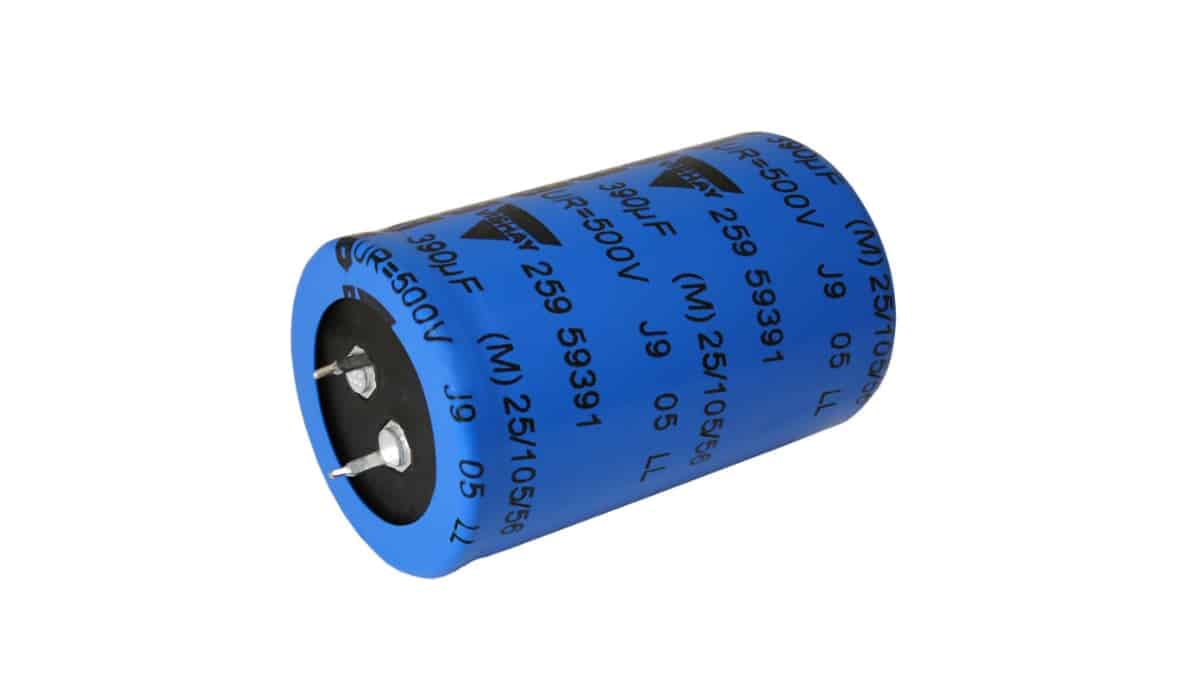
Vishay has extended its 259 PHM-SI series of snap-in aluminum electrolytic capacitors with 550 V and 600 V versions for buffering, filtering and energy storage.
The Vishay aluminum electrolytic capacitors higher voltage options expand capacitor-bank choices for industrial converters, renewable-energy systems and charging equipment, where bus voltage, ripple current and thermal conditions govern selection.
Key features and benefits
- Rated voltage options of 550 V and 600 V extend the existing 259 PHM-SI family.
- Representative configurations include 330 µF at either voltage in a nominal 35 mm × 45 mm case, plus 470 µF / 550 V and 390 µF / 600 V in a nominal 35 mm × 55 mm case.
- These four configurations support rated RMS ripple currents from 2.14 A to 2.58 A at 100 Hz and +105 °C.
- Useful life exceeds 3000 h at +105 °C with rated voltage and rated ripple current applied.
- Two-terminal and three-terminal keyed-polarity snap-in versions support PCB mounting.
- Construction uses a polarized, non-solid electrolyte in a cylindrical aluminum case with a blue insulating sleeve.
Technical highlights
Series-wide ratings
The family spans 200 V to 600 V, with capacitance and case-size choices dependent on voltage. The full capacitance range should therefore not be treated as available at every voltage rating.
| Parameter | Value | Conditions or scope |
|---|---|---|
| Rated voltage range | 200 V to 600 V | Series-wide |
| Rated capacitance range | 39 µF to 2200 µF | At 100 Hz |
| Capacitance tolerance | ±20% | Rated capacitance |
| Nominal case sizes, ØD × L | 22 × 25 to 35 × 60 mm | Series-wide |
| Category temperature range | −40 °C to +105 °C | Impedance relevant at −40 °C |
| Useful life | >3000 h | +105 °C; rated voltage and ripple |
| Sectional specification | IEC 60384-4 / EN 130300 | Series basis |
| Climatic category | 25 / 105 / 56 | 500 V to 600 V versions |
The 500 V to 600 V versions have an IEC 60068 climatic category of 25 / 105 / 56. Operation extends to −40 °C, but impedance at that temperature needs consideration when assessing cold-start behaviour.
Selected 550 V and 600 V configurations
| Rated voltage / capacitance | Nominal case, ØD × L | Rated ripple current | Maximum ESR |
|---|---|---|---|
| 550 V / 330 µF | 35 × 45 mm | 2.14 A | 475 mΩ |
| 600 V / 330 µF | 35 × 45 mm | 2.16 A | 740 mΩ |
| 550 V / 470 µF | 35 × 55 mm | 2.58 A | 345 mΩ |
| 600 V / 390 µF | 35 × 55 mm | 2.28 A | 730 mΩ |
Ripple-current ratings apply at 100 Hz and +105 °C. ESR values apply at 100 Hz and +20 °C.
The 330 µF options illustrate why voltage rating should not be assessed in isolation. Both occupy the same nominal case size and have similar rated ripple currents, but their maximum ESR values differ. In the 35 mm × 55 mm case, the 550 V option provides 470 µF, while the 600 V option provides 390 µF.
Ripple current and thermal behaviour
Capacitor ripple current produces internal heating, so the frequency spectrum matters alongside the RMS current. The series uses frequency-dependent multipliers to relate permissible ripple current to its 100 Hz rating.
| Ripple frequency | Ripple-current multiplier |
|---|---|
| 50 Hz | 0.8 |
| 100 Hz | 1.0 |
| 120 Hz | 1.05 |
| 200 Hz | 1.2 |
| 1 kHz | 1.4 |
| ≥10 kHz | 1.5 |
Converter selection should account for both low-frequency rectifier ripple and switching-frequency current. Ambient temperature, ripple heating and cooling conditions must be assessed together when estimating useful life. The series supports estimated application life exceeding 10 years of continuous operation at ambient temperatures up to +60 °C; the actual duty profile and ripple loading determine the applicable lifetime estimate.
Typical applications
Motor drives and industrial power conversion
Target applications include motor controls, small drives, industrial heating and cooling, welding, cutting and melting equipment. In a motor-drive DC link, the capacitor bank buffers energy between the rectifier and inverter while filtering current components from both stages.
The 550 V and 600 V options extend the available voltage choices for this position. Selection still depends on the required minimum capacitance, the frequency-adjusted ripple current and the temperature around the capacitor bank.
Solar inverters and renewable-energy systems
Solar PV inverters and wind turbines are target applications. In a solar inverter, the DC-link capacitor operates under different stresses during power conversion and off-line conditions: ripple current and temperature govern much of the operating-life assessment, while the unloaded source voltage affects the required voltage rating.
The higher voltage options also support consideration of fewer capacitors in series on 800 V to 1100 V buses. Series-connected capacitor balancing remains a separate design requirement: leakage-current differences influence steady-state voltage sharing, while capacitance differences influence transient sharing.
Charging, UPS and other equipment
Additional target applications include wallboxes, stationary EV chargers, UPS equipment, UV water-treatment lamp drivers, plasma cutters, switch cabinets and medical instrumentation. Buffering, filtering and energy-storage requirements in these systems should be matched to the selected capacitor’s voltage, capacitance, ripple-current and useful-life ratings.
Design-in notes for engineers
- Assess voltage sharing across series-connected devices under both steady-state and transient conditions. A higher individual voltage rating does not itself establish balanced operation.
- Use the ±20% capacitance tolerance when checking minimum required capacitance and transient voltage distribution.
- Apply the frequency-dependent ripple multipliers before assessing thermal loading. Include local ambient temperature, nearby heat sources and airflow in the lifetime calculation.
- Allocate mechanical space from maximum dimensions rather than nominal case size. The nominal 35 mm × 45 mm case has a maximum diameter of 36 mm and maximum body length of 47 mm; the nominal 35 mm × 55 mm case has corresponding maxima of 36 mm and 57 mm.
- Match the PCB footprint to the terminal option. The two-terminal version uses 10 mm ±0.1 mm hole spacing and 2 mm ±0.1 mm hole diameters. The keyed three-terminal version adds an offset hole; both negative-terminal pins are electrically connected.
- Validate the final capacitor-bank selection under the actual electrical, thermal and mechanical operating conditions before production release.
Availability
Production quantities of the extended 259 PHM-SI series are available, with regional lead times of 12 to 18 weeks as of November 2026. Small sample quantities are available through catalog distributors.
Further reading
- Estimating and Modelling Lifetime of Aluminum Electrolytic Capacitors for any Ripple Current and Temperature
- Aluminium Electrolytic Capacitors Accelerated Lifetime Modeling
Source
This article is based on the Vishay product announcement and official product documentation. Engineers should refer to the current manufacturer datasheet for final design and qualification.
References
- 259 PHM-SI — Aluminum Electrolytic Capacitors, Power High Ripple Current Miniaturized Snap-In, Vishay BCcomponents, September 16, 2026.
- Vishay Intertechnology Extends 259 PHM-SI Series of Snap-in Power Aluminum Capacitors With 550 V and 600 V Ratings, Vishay Intertechnology, November 17, 2026.
- 259 PHM-SI Product Information, Vishay BCcomponents.
- The Art and Science of Using Aluminum Electrolytic Capacitors — Balancing, Vishay Intertechnology, 2024.
- Aluminum Capacitors Lifetime Calculator — Help, Vishay Intertechnology.
- Aluminum Electrolytic Capacitors in Power Applications, Vishay Intertechnology.