Passive Components Blog
No Result
View All Result
  • Home
  • News
    • All
    • Aerospace & Defence
    • Antenna
    • Applications
    • Automotive
    • Capacitors
    • Circuit Protection Devices
    • electro-mechanical news
    • Filters
    • Fuses
    • Inductors
    • Industrial
    • Integrated Passives
    • inter-connect news
    • Market & Supply Chain
    • Market Insights
    • Medical
    • Modelling and Simulation
    • New Materials & Supply
    • New Technologies
    • Non-linear Passives
    • Optoelectronics and Isolation
    • Oscillators
    • Passive Sensors News
    • Resistors
    • RF & Microwave
    • Telecommunication
    • Weekly Digest
    Siemens executives Markus Grabmeier and Barry Powell with Skeleton Technologies CEO Taavi Madiberk at the investment announcement

    Siemens Backs Skeleton’s US AI Power Manufacturing Expansion

    Concept illustration of an LTCC antenna module with multilayer ceramic substrate, antenna elements and an integrated beamforming IC

    Murata LTCC 6G Antenna Module Demonstrates 135 GHz Operation

    TDK X series surface-mount multilayer varistors with ceramic chip bodies and metal end terminations

    TDK X Series SMD Varistors for Industrial Transient Protection

    Littelfuse TP7.0SMD-XC automotive TVS diodes with black surface-mount bodies and silver end terminals.

    Littelfuse Introduces Extremely Low Clamping Voltage TVS Diodes for Automotive Protection

    Supercapacitor LSM production

    LS Materials Wins $51.5M AI Data Center Supercapacitor Order

    Features of BCZT and strontium titanate dielectric layers in a thin-film superlattice

    Relaxor superlattice capacitors approach 99% efficiency

    Stackpole RMAN thick-film chip resistors with rectangular bodies and metal end terminations

    Stackpole 2512 AlN Thick-Film Resistors Rated up to 3.5 W

    ECIA September 2026 Industry Pulse electronic component trends and sentiment report

    ECIA September 2026 Pulse: Growth Holds, Supply Pressure Persists

    Wk 39 Electronics Supply Chain Digest

    Trending Tags

    • Ripple Current
    • RF
    • Leakage Current
    • Tantalum vs Ceramic
    • Snubber
    • Low ESR
    • Feedthrough
    • Derating
    • Dielectric Constant
    • New Products
    • Market Reports
  • Knowledge Blog
  • Dossiers
    • Aerospace and Defense Passive Components Dossier
    • AI Hardware Dossier
    • Automotive Dossier
    • Industrial Robotics Dossier
    • Power Converter Dossier
    • Capacitor Dossier
    • Circuit Protection Dossier
    • Inductor Dossier
    • Resistor Dossier
    • Silicon Capacitors and Integrated Passives Dossier
  • Suppliers
    • Who is Who
  • PCNS
    • PCNS 2025
    • PCNS 2023
    • PCNS 2021
    • PCNS 2019
    • PCNS 2017
  • Events
  • Home
  • News
    • All
    • Aerospace & Defence
    • Antenna
    • Applications
    • Automotive
    • Capacitors
    • Circuit Protection Devices
    • electro-mechanical news
    • Filters
    • Fuses
    • Inductors
    • Industrial
    • Integrated Passives
    • inter-connect news
    • Market & Supply Chain
    • Market Insights
    • Medical
    • Modelling and Simulation
    • New Materials & Supply
    • New Technologies
    • Non-linear Passives
    • Optoelectronics and Isolation
    • Oscillators
    • Passive Sensors News
    • Resistors
    • RF & Microwave
    • Telecommunication
    • Weekly Digest
    Siemens executives Markus Grabmeier and Barry Powell with Skeleton Technologies CEO Taavi Madiberk at the investment announcement

    Siemens Backs Skeleton’s US AI Power Manufacturing Expansion

    Concept illustration of an LTCC antenna module with multilayer ceramic substrate, antenna elements and an integrated beamforming IC

    Murata LTCC 6G Antenna Module Demonstrates 135 GHz Operation

    TDK X series surface-mount multilayer varistors with ceramic chip bodies and metal end terminations

    TDK X Series SMD Varistors for Industrial Transient Protection

    Littelfuse TP7.0SMD-XC automotive TVS diodes with black surface-mount bodies and silver end terminals.

    Littelfuse Introduces Extremely Low Clamping Voltage TVS Diodes for Automotive Protection

    Supercapacitor LSM production

    LS Materials Wins $51.5M AI Data Center Supercapacitor Order

    Features of BCZT and strontium titanate dielectric layers in a thin-film superlattice

    Relaxor superlattice capacitors approach 99% efficiency

    Stackpole RMAN thick-film chip resistors with rectangular bodies and metal end terminations

    Stackpole 2512 AlN Thick-Film Resistors Rated up to 3.5 W

    ECIA September 2026 Industry Pulse electronic component trends and sentiment report

    ECIA September 2026 Pulse: Growth Holds, Supply Pressure Persists

    Wk 39 Electronics Supply Chain Digest

    Trending Tags

    • Ripple Current
    • RF
    • Leakage Current
    • Tantalum vs Ceramic
    • Snubber
    • Low ESR
    • Feedthrough
    • Derating
    • Dielectric Constant
    • New Products
    • Market Reports
  • Knowledge Blog
  • Dossiers
    • Aerospace and Defense Passive Components Dossier
    • AI Hardware Dossier
    • Automotive Dossier
    • Industrial Robotics Dossier
    • Power Converter Dossier
    • Capacitor Dossier
    • Circuit Protection Dossier
    • Inductor Dossier
    • Resistor Dossier
    • Silicon Capacitors and Integrated Passives Dossier
  • Suppliers
    • Who is Who
  • PCNS
    • PCNS 2025
    • PCNS 2023
    • PCNS 2021
    • PCNS 2019
    • PCNS 2017
  • Events
No Result
View All Result
Passive Components Blog
No Result
View All Result

How Much Gold is Needed for Connector Plating

17.12.2024
Reading Time: 6 mins read
A A

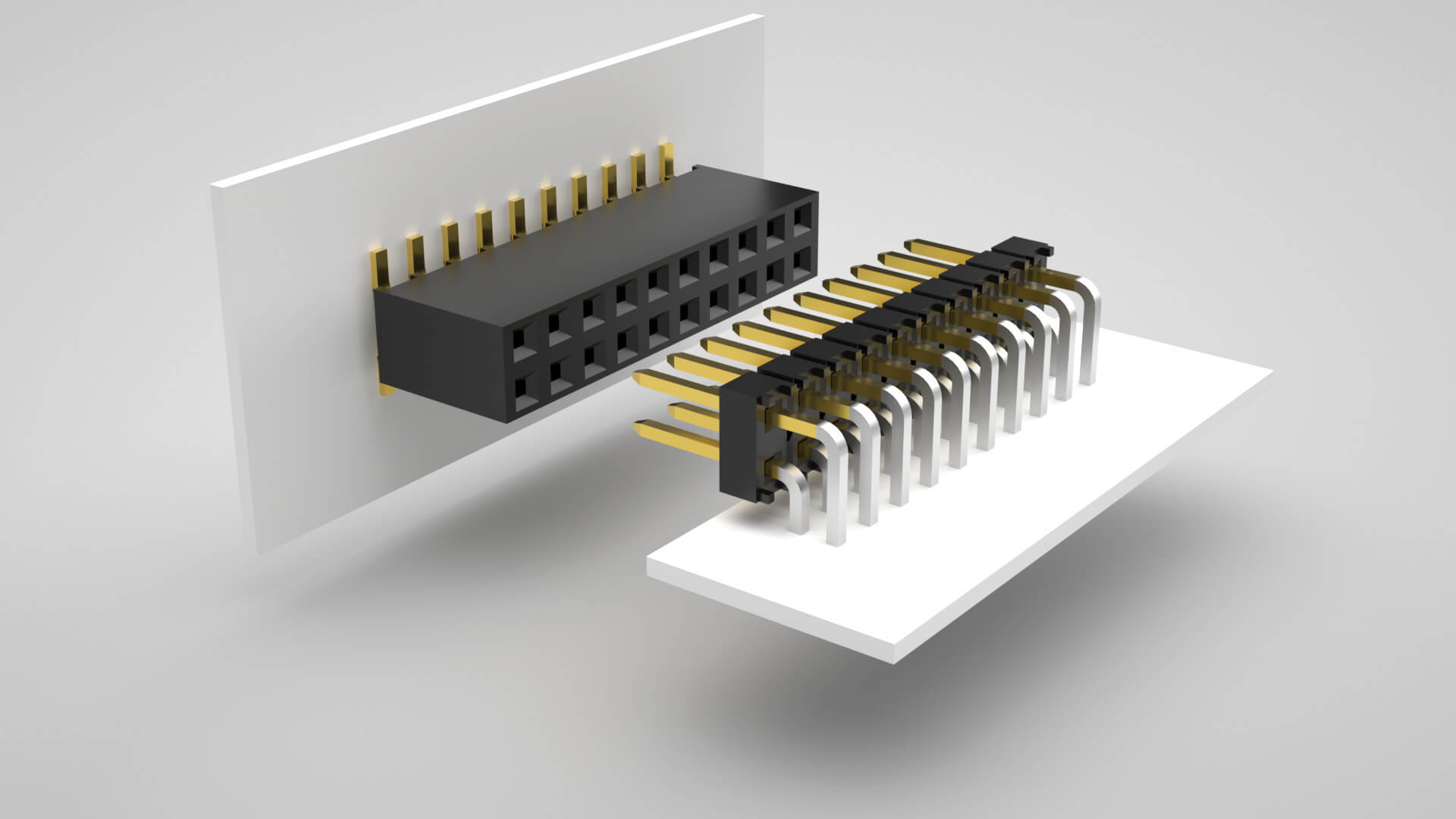
This blog written by Samtec discusses how much gold is needed to specify on the connector pins plating. 

Gold Plating Is A Major Cost Driver

The major costs in a connector set are:

RelatedPosts

Samtec Links Automotive Connector Demands to Software-Defined Cars

Samtec 100-CM 1.0 mm RF Connectors Extend to 120 GHz

Samtec AcceleRate Slim ARC6 Cable Assemblies with New Signaling Options

  • the plastic body
  • the pins
  • the plating on the pins
  • the labor to assemble it
  • the packaging

And on most connectors – the bigger ticket items are the pins and the plating.

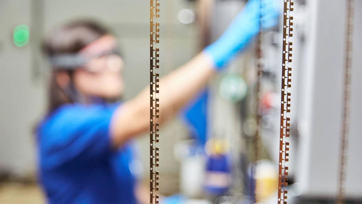
For example, on a micro-pitch, high-density interconnect product, the pins and plating may account for about 25% – 30% of the total cost of the connector. However, on a basic 2.54 mm centerline terminal strip (“header”), it can account for up to 60% – 70% of the total cost of the connector.

That’s because the relative size of the plastic body on a miniature, mold-to-position micro connector is almost always larger than the body on a basic cut-to-position strip-line connector. Conversely, on a basic 2.00 or 2.54 mm pitch strip header and socket, the pins are larger and therefore require more plating.  And, of course, the pins are going to cost more if you’re using gold plating.

So, selecting the right pin and plating significantly impacts the cost of the connector system.

Why Use Gold Plating?

Gold is generally specified for high reliability, low voltage, or low current applications. Gold is used in high-cycle applications because it’s rugged and has excellent wear properties (here’s an example of a high-cycle connector). Samtec’s gold is alloyed with cobalt, which increases the hardness. We also recommend gold for hostile environments, because it will remain free of oxides which could cause an increase in contact resistance.

Gold is a noble metal, which means it doesn’t react much to its environment. Also, sometimes gold is a “matter of necessity” in that as connectors shrink in size, the contacts are too small to generate much normal force. So, low normal forces guide the need for Au plating. 

The disadvantages of gold are primarily cost, then porosity at thinner plating levels, and some nuances regarding solderability. Specifically, many customers successfully solder all gold-plated pins to the PCB. But, they are not soldering to the Au, because the Au dissolves in the molten solder. They are soldering to the nickel under the Au. So, technically, it is correct to say Au has poor solderability. 

How Much Gold Plating Do I Need?

The quick answer is to use whatever amount meets your system requirements at the lowest cost. In other words, make sure it works and meets your quality design specifications, but don’t over-design on the plating.

But how much gold is enough? Unfortunately, there’s no answer that we can guarantee is right for every application. But, for simplicity’s sake, we can tell you that the vast majority of Samtec customers who use gold plating can be divided into three categories: 

  • very light gold (about 3 µ”, or “flash”)
  • “standard” gold (10 µ”)
  • and heavy gold (30 µ” or more).

Very light gold, or “flash” gold plating, is used in applications where the connector set will have a relatively easy life, AKA, an office environment. An “easy life” means the mated connector set is:

  • Not going to be cycled, or plugged and unplugged, much. Like maybe 10 – 15 times, depending on the contact selected.
  • In a clean environment where it’s not subject to any corrosive chemicals or vapors.
  • Not subject to temperature swings, or higher temperatures, and it’s in a low-humidity setting.   
  • Not subject to shock and vibration, and it won’t be dropped or manhandled.

Conversely, heavy gold is used in applications where the connector set is:

  • Going to be cycled, or plugged and unplugged frequently. This refers to 50 cycles or more, depending on the contact system.
  • In a harsh environment where it is subject to high temperature, high humidity, swings in temperature and humidity, and corrosive chemicals or vapors.
  • The application is subject to higher shock and vibration.
  • The equipment’s failure will lead to catastrophic results, like the loss of life or injuries.

It’s interesting that the requirements that would qualify a connector for “standard” gold plating are arguably the most vague. -L plating (usually 10 µ” of gold in the contact area) is the plating option most Samtec customers select. In other words, the majority of Samtec customers use “standard” gold thickness — 10 µ” of gold — and it works just fine in their applications.

BTW, I mention three of our gold plating options above. Many Samtec products are available with a wide variety of plating options, from all tin, to gold flash, to extra heavy gold, to tin/lead, and others.

It’s Much More Than Just Plating Thickness

If you’re still reading, please stay with me for another minute or two. This is important stuff:

First, the plating thickness is not the only factor that determines the success of a mated connector system. It’s essential that the contact system selected meets the demands of the application. Samtec offers several contact systems, on a variety of centerlines and stack heights, depending on your design requirements. For example, a Samtec Tiger Eye™ contact system is designed for high reliability, high cycle applications. It features a multi-finger contact – with either three or four points of contact – made of heat-treated beryllium copper. With the right plating, this contact system has been tested to over 1,000 cycles. Other contact systems, made of lesser metals and with fewer points of contact, will not reach 1,000 cycles even with 50 µ” of gold.

Second, you must take into account other specifications like the normal force of the mated connector set, possible effects of dissimilar metals and galvanic corrosion, underplating and their thicknesses, solderability, the operating temperature of the connector and its impact on performance, voltage and amperage, amount of vibration, and other factors. It’s not just the plating!

Third, if your system requires your connectors to be tested beyond typical industry standards and specifications, many of which are common requirements for harsh environment applications/industries, check out our Severe Environment Testing (SET) initiative.

Driven by demands for high-functioning commercial standard interconnects, SET has proven beneficial in providing performance confidence, not only for rugged Mil/Aero industries and applications, but also for Automotive, Industrial, and Medical applications.

And, if your application requires very high mating cycles, Samtec ELP products are tested to rigorous standards that evaluate contact resistance in simulated storage and field conditions. These connectors have passed a nasty 10-year Mixed Flowing Gas (MFG) test, are tested to very high-mating cycles (250 to 2,500), and a variety of connector types and pitches available.

Related

Source: Samtec

Recent Posts

Image credit: Samtec

How to Match the Right Connector with Protocol Requirements

6.11.2025
81

Polymer Materials and Processing

11.8.2025
284

Basic PCB Technology Overview

1.7.2025
71

What is RF Connector

17.12.2024
106

Feedback from Connector Failure Analysis

10.10.2025
163

Understanding Cable Skew: A Key to High-Speed Signal Integrity

25.7.2025
217

RF Connector Types: How To Choose the Right One

24.4.2026
1.4k

EMI Shielding Considerations with Connectors

9.4.2025
404

Microwave Multi Line Connectors Mounting and Handling Precautions

11.8.2025
47

Upcoming Events

Oct 19
15:00 - 16:00 CEST

ESCC-qualified Pt Temperature Sensors for Space Applications

Oct 27
15:00 - 16:00 CET

Heraeus Electronics Webinar: What materials perform when failure is not an option?

Oct 27
16:00 - 17:00 CET

Power Inductor technologies

View Calendar

Popular Posts

  • Buck Converter Design and Calculation

    0 shares
    Share 0 Tweet 0
  • Boost Converter Design and Calculation

    0 shares
    Share 0 Tweet 0
  • LLC Resonant Converter Design and Calculation

    0 shares
    Share 0 Tweet 0
  • Flyback Converter Design and Calculation

    0 shares
    Share 0 Tweet 0
  • Capacitor Charging and Discharging

    0 shares
    Share 0 Tweet 0
  • Audio Capacitors: Choosing Capacitors for Crossover Circuits

    0 shares
    Share 0 Tweet 0
  • MLCC and Ceramic Capacitors

    0 shares
    Share 0 Tweet 0
  • Resistor Symbols

    0 shares
    Share 0 Tweet 0
  • Passive Low Pass Filters: Fundamentals and EMI Design

    0 shares
    Share 0 Tweet 0
  • RF Connector Types: How To Choose the Right One

    0 shares
    Share 0 Tweet 0

Newsletter Subscription


Passive Components Blog

© 2015–2026
All rights reserved

  • Home
  • Privacy Policy
  • EPCI Membership & Advertisement
  • About

No Result
View All Result
  • Home
  • Knowledge Blog
  • Dossiers
  • PCNS

© 2015–2026
All rights reserved