

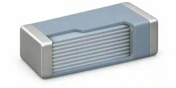


Aluminum electrolytic capacitors provide high capacitance in a compact package and are widely used for power-supply smoothing, filtering and energy storage.
This article explains their construction, wet, polymer and hybrid technologies, electrical characteristics, lifetime limitations and selection requirements for design engineers and component engineers.
Key Takeaways
- The dielectric is a thin aluminum oxide layer on an etched aluminum anode. The electrolyte contacts this oxide and forms part of the cathode system; it is not the dielectric.
- Wet aluminum electrolytic capacitors combine high capacitance and economical bulk energy storage, but their electrolyte resistance and gradual electrolyte loss influence low-temperature performance and useful life.
- Conductive polymer types generally offer lower ESR and less temperature-dependent resistance. Hybrid types combine conductive polymer with liquid electrolyte, so their operating limits and ageing mechanisms must be assessed separately.
- Check peak terminal voltage, polarity, ripple-current spectrum, ESR, operating temperature and assembly conditions against the exact series datasheet. Do not treat surge voltage or an observed reverse-voltage tolerance as a continuous operating allowance.
- Lifetime estimates require the manufacturer’s model and the application’s thermal conditions. The familiar doubling of wet-capacitor life for each 10 °C temperature reduction is an approximation, not a universal guarantee.
Construction, Features and Manufacturing Process of Aluminum Electrolytic Capacitors
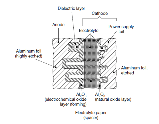
The high capacitance of an aluminum electrolytic capacitor results from a large etched anode surface and a very thin aluminum oxide dielectric. Its practical behaviour also depends on the electrolyte, current collectors, separator, terminals and enclosure. Understanding these elements helps explain the differences between wet, solid polymer and hybrid constructions. [1]
Anode, dielectric and electrolyte
The anode foil is etched to increase its effective surface area and then anodically formed to grow an insulating aluminum oxide layer. The electrolyte contacts the oxide throughout the etched structure, while the cathode foil collects current from the electrolyte. In conventional wet constructions, electrolyte-impregnated separator paper prevents direct metallic contact between the foils and acts as an electrolyte reservoir. [1]
The oxide thickness and the accessible etched surface determine the available capacitance at a given voltage rating. Increasing the formation voltage requires a thicker oxide and changes the usable tunnel geometry. Consequently, capacitance density cannot be compared independently of rated voltage, temperature range, ESR and lifetime requirements.
Most aluminum electrolytic capacitors are polarized. Reversing the applied voltage can produce excessive leakage current, electrochemical reactions, heating and gas generation. Use a specified non-polar construction or another suitable capacitor technology where the application requires voltage reversal; a polarized capacitor is not a general-purpose AC capacitor. [1]
Self-healing and its limits
In a wet capacitor operating with the correct polarity, leakage current at a local dielectric defect can support further oxide formation and reduce the defect’s conductivity. This electrochemical repair mechanism helps maintain the dielectric, but it does not make the component immune to overvoltage, reverse polarity, overheating or contamination. Electrolyte composition and the availability of the reactants needed for oxide repair are important. [1, 2]
Solid conductive electrolytes can exhibit a different local fault-isolation mechanism involving a reduction in conductivity near a defect. This must not be interpreted as guaranteed recovery from a short circuit. The failure behaviour and protection requirements depend on the particular construction and the energy available from the circuit.
Electrolyte resistance and temperature
Liquid electrolytes conduct through mobile ions. Their conductivity depends on formulation, concentration, viscosity and temperature, as well as the geometry of the current path through the separator and etched structure. At low temperature, increasing electrolyte resistance generally raises equivalent series resistance, or ESR, and reduces the capacitance accessible at a given measurement frequency. [1]
Conductive polymers carry charge electronically and usually reduce the electrolyte contribution to ESR. Nevertheless, total ESR also includes losses associated with the dielectric, foils, tabs, contacts and terminals. A low room-temperature ESR value does not replace the need to check frequency and temperature characteristics.
Wet and hybrid capacitors contain liquid electrolyte that can be lost gradually through the sealing system. The rate depends on construction, temperature and operating conditions. Solid polymer types do not share this liquid-electrolyte dry-out mechanism, but they still have finite life and environmental limitations.
Packages and termination styles
Package choice affects assembly, cooling, inductance, mechanical support and serviceability. Common termination styles include:
- Surface-mount aluminum cans, often described as V-chip types, for PCB assembly.
- Radial leads for through-hole mounting, with both terminals at one end of the can.
- Axial leads for through-hole mounting, with terminals at opposite ends.
- Snap-in terminals for larger PCB-mounted power capacitors.
- Press-fit terminals where offered for the intended board and assembly process.
- Screw terminals for larger power capacitors and capacitor banks.
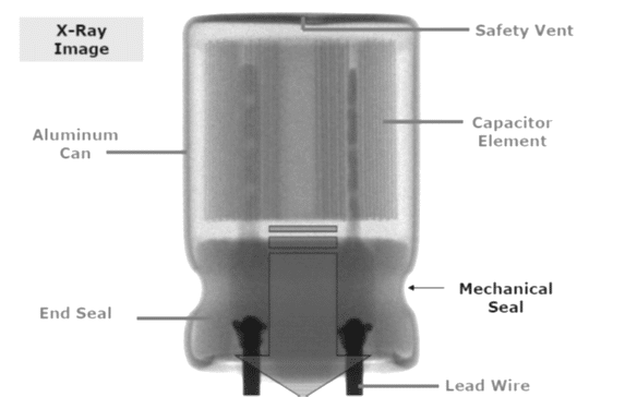
Wound foil elements in aluminum cans are common in both leaded and surface-mount products. Figures 1 and 2 show the wound element and a representative construction. Stacked foil constructions are also used in solid polymer chip capacitors.
Wet, polymer, hybrid and historical solid electrolytes
The main technologies discussed here are wet aluminum electrolytic capacitors, solid conductive polymer capacitors and hybrid capacitors containing both polymer and liquid electrolyte. Organic semiconductor salt electrolytes based on TCNQ and manganese dioxide solid aluminum capacitors are included later for historical comparison and legacy-equipment support. TCNQ salt is a solid organic semiconductor electrolyte, not a generic gel category.
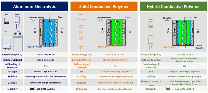
Hybrid technology can offer a useful combination of low ESR, ripple-current capability and electrochemical oxide repair. It is not a universal replacement for either wet or solid polymer technology. Selection depends on voltage, leakage current, temperature, expected service life, size, assembly process and cost.
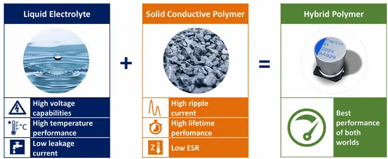
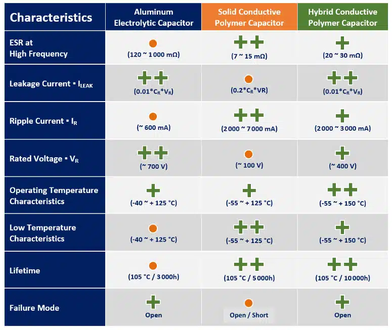
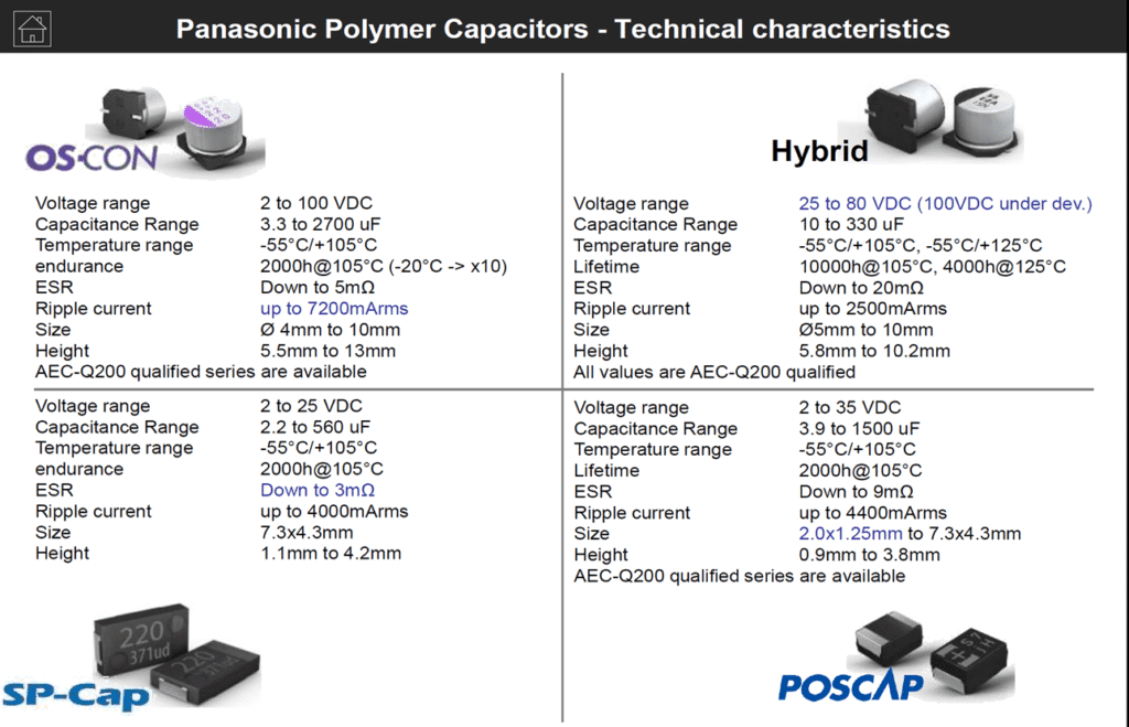
Commercial family names must be interpreted using current manufacturer documentation. Current Panasonic OS-CON products use conductive polymer; the name must not be used as a synonym for historical TCNQ electrolyte. SP-Cap identifies an aluminum conductive polymer family, while POSCAP identifies tantalum conductive polymer capacitors rather than aluminum capacitors. [3]
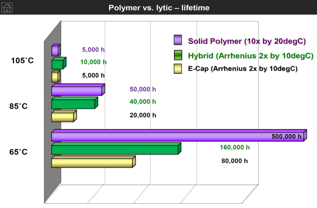
Temperature-dependent life comparisons are useful only when their assumptions are understood. Different technologies and series may use different acceleration models, rated endurance conditions and end-of-life criteria. Figure 7 therefore provides historical comparison context, not a common lifetime equation that can be applied to every wet, polymer and hybrid capacitor.
DCL and balancing of series-connected capacitors
DC leakage current, abbreviated DCL, depends on voltage, temperature, time after energisation and the capacitor’s previous operating and storage history. Datasheet leakage limits and settled operating leakage are not necessarily the same. Compare leakage specifications only when their test voltage, temperature, conditioning and measurement time are equivalent. [2]
In a series-connected DC-link bank, equal nominal capacitance does not guarantee equal steady-state voltage. Differences in leakage current can unbalance the voltage distribution. Passive balancing resistors or an appropriate active balancing circuit may therefore be required. During charging and other transients, capacitance tolerance and circuit impedances also influence voltage sharing.
Choose balancing resistors using the expected leakage-current mismatch at operating temperature, resistor tolerance, permissible capacitor voltage and resistor power dissipation. Check resistor working voltage as well as resistance and wattage. Active balancing does not automatically provide a safe discharge path when the equipment is switched off. [2]
Manufacturing process
For a conventional wound wet capacitor, manufacture begins with etched and formed anode foil, cathode foil and separator paper. The mother rolls are slit to the required width. Tabs or terminal connections are attached, and the materials are wound into a capacitor element. The exact sequence and connection method depend on the product construction. [1]
The wound element is impregnated with electrolyte, commonly using vacuum to help fill the separator and etched structure. It is then installed in the case and sealed. The sealing system must retain electrolyte while managing the pressure associated with the capacitor’s electrochemical behaviour.
Electrical ageing or post-forming repairs oxide damage associated with cutting, winding and connection operations. Inspection and electrical testing then establish whether capacitance, leakage current, ESR or impedance meet the product specification. Sleeving, marking and packaging complete the process; taped packaging applies where appropriate to the component format. [1]

Wet Aluminum Electrolytic Capacitors
Wet aluminum electrolytic capacitors remain important for bulk smoothing, energy storage and power conversion, particularly where high capacitance or higher voltage makes solid polymer alternatives unsuitable. Their performance depends strongly on electrolyte properties, temperature, frequency and the thermal conditions established by ripple current. [1]
Sealing, gas generation and pressure relief
Electrochemical reactions can generate hydrogen within a wet aluminum electrolytic capacitor. Conventional sealing systems are generally not fully hermetic, and many constructions include a pressure-relief vent. Electrolyte chemistry, gas management and sealing must be considered together; the presence of liquid electrolyte alone does not establish the packaging requirements of every specialised capacitor. [1]
A vent is a safety feature, not a normal operating outlet that permits electrical overload. Keep the specified clearance around it and do not obstruct it with adhesive, potting compound, mounting hardware or adjacent components. Follow the selected series instructions for orientation and enclosure design.
Impedance, capacitance and application scope
Datasheets commonly show impedance against frequency at different temperatures. At low frequency, capacitive reactance dominates. Around the impedance minimum, ESR becomes important; above self-resonance, equivalent series inductance increasingly determines the terminal impedance. The locations of these regions depend on construction, capacitance, temperature and the frequency-dependent accessible capacitance. [1]
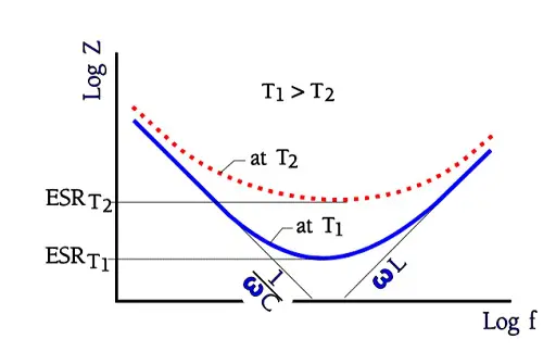
Nominal capacitance is specified under defined measurement conditions. The initial tolerance is not the complete operating variation: temperature, frequency and ageing can change the capacitance available in the circuit. Select the minimum required capacitance using the relevant worst-case conditions rather than the nominal marking alone.
For bulk rectifier smoothing and DC-link energy storage, capacitance, voltage rating, ripple-current capability and useful life are central requirements. For SMPS output filtering, ESR and impedance across the switching spectrum are also important. For signal coupling, check polarity throughout the signal swing, leakage current and the resulting low-frequency response. Timing applications with large time constants are possible, but leakage, tolerance and dielectric absorption limit precision. [1]
Polarized wet capacitors must operate with the specified polarity. Do not use a generic reverse-voltage figure as an allowable operating condition. Check that the complete terminal waveform, including ripple and start-up or shutdown transients, remains within the selected product’s requirements.
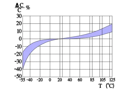
Capacitance versus temperature
At low temperature, the electrolyte becomes more resistive and some of the etched anode structure becomes less accessible at the measurement frequency. The measured series capacitance can therefore decrease while ESR rises. Temperature range and low-temperature impedance limits are series-specific; the upper temperature rating alone does not describe cold-start performance. [1]
Capacitance versus frequency
The electrolyte-filled etch tunnels behave as distributed resistance-capacitance networks. As frequency increases, deeper regions contribute less to the measured capacitance. Fine etching used for high capacitance density can make this effect more pronounced, but its magnitude must be taken from the selected series rather than inferred from capacitance or voltage alone. [1]

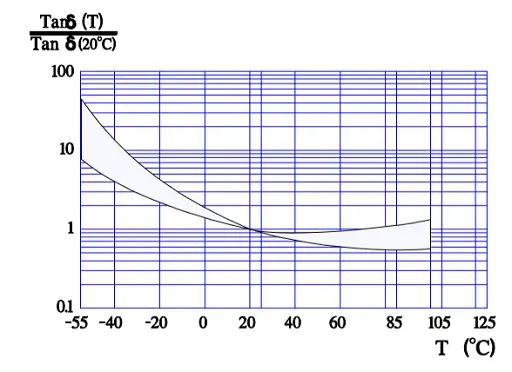
Dissipation factor versus temperature
Dissipation factor, tan δ, describes losses relative to capacitive reactance. In the capacitive operating region of the series equivalent circuit, Eq. (1) relates tan δ to frequency f, measured series capacitance Cs and ESR. Frequency is in hertz, capacitance in farads and ESR in ohms; tan δ is dimensionless.
At a fixed frequency, increasing ESR generally increases dissipation factor. However, Cs also changes with temperature, especially under cold conditions, so the normalised ESR and tan δ curves need not have identical shapes. Do not use a low-frequency tan δ limit as a substitute for ESR at the switching frequency.
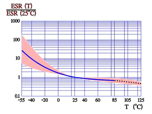
ESR versus temperature
For many wet capacitor constructions, electrolyte resistance dominates the low-temperature increase in ESR. This is important during cold start, when ripple heating and transient voltage excursions may differ substantially from room-temperature behaviour. Metallic and dielectric loss contributions also matter, so a single inverse-temperature rule does not describe every frequency and operating condition. [1]
ESR versus frequency
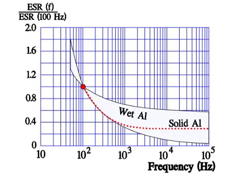
The normalised ESR in Figure 14 is the ESR at the frequency of interest divided by its value at 100 Hz. The decreasing low-frequency contribution reflects dielectric and distributed-structure losses. At higher frequency, electrolyte and conductive-path resistance become more important. Use the specified ESR or impedance at the frequency relevant to the application.
ESR and ripple current
AC ripple current produces internal heating through ESR. Eq. (2) gives the resistive loss P for a single-frequency RMS ripple current Irms, using ESR at that frequency and the relevant operating temperature. P is in watts and Irms is in amperes. [1]
For a ripple waveform containing distinct frequency components, Eq. (3) estimates the total resistive loss by adding the contribution from each component. Here Ik,rms is the RMS current of component k and fk is its frequency. Use the manufacturer’s prescribed method where frequency correction factors or a more detailed model are supplied.
Ripple-current ratings apply at specified frequency, temperature and cooling conditions. There is no universal allowable internal temperature rise for every aluminum electrolytic capacitor. Do not assume that a frequency multiplier, ambient-temperature multiplier or airflow correction from one series applies to another.
Consider the original comparison between 100 Hz and 10 kHz. Assume that ESR at 10 kHz is half its value at 100 Hz and that the permitted loss remains unchanged. Eq. (4) gives the corresponding current ratio.
Using the rounded multiplier 1.4 gives a loss ratio of 1.4² × 0.5 = 0.98, or approximately the original loss. This is an explanatory example, not permission to exceed a datasheet rating. It assumes the stated ESR ratio, equivalent thermal conditions and no additional limiting mechanism.
Leakage current versus temperature and voltage
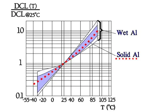
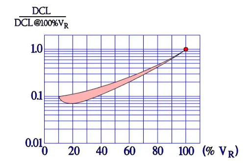
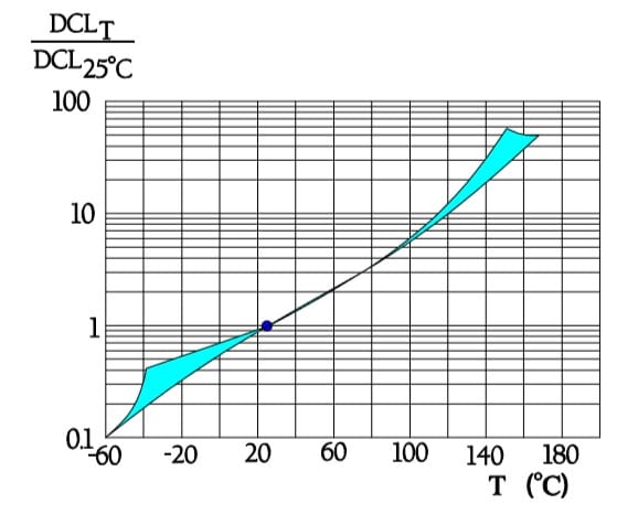
Leakage current generally increases with temperature and applied voltage, and decreases after voltage is applied as the capacitor settles and local oxide repair proceeds. Its value also depends on storage and operating history. A leakage-current reading is meaningful only with its voltage, temperature, elapsed time and conditioning procedure stated. [1, 2]
Figures 15 and 16 illustrate these dependencies. Their normalised curves must not replace the selected series leakage limit or be treated as a universal multiplier across the complete temperature range.
Heat generation and hot-spot temperature
Internal ripple-current loss raises the winding temperature above the surrounding ambient. The hottest region is not necessarily represented by a surface measurement, particularly in a large can. Cooling conditions, mounting, heat flow through the terminals and nearby heat sources all influence the relationship between ambient, can and winding temperatures. [1]
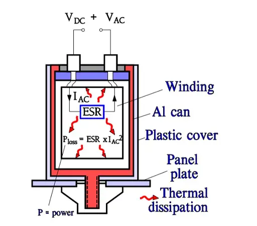
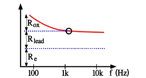
Figure 18 separates the loss contributions conceptually. Rox represents the equivalent contribution from dielectric oxide losses, Re represents electrolyte and separator-path resistance, and Rlead represents conductive-path resistance. Rox is an AC loss representation; it must not be confused with the parallel insulation resistance used to describe DC leakage.
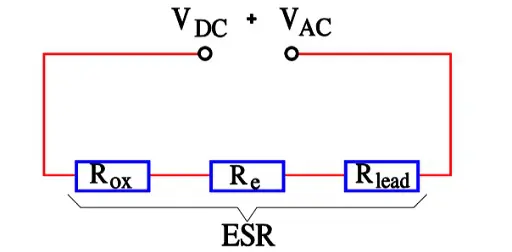
The relative contributions change with frequency. Figure 19 illustrates a declining equivalent oxide-loss contribution, but it does not establish a universal frequency above which dielectric loss disappears.
Where a valid lumped thermal model is available, Eq. (5) relates hot-spot temperature Th, local ambient temperature Ta, internally dissipated power P and effective hot-spot-to-ambient thermal resistance Rθ,h-a. Thermal resistance is expressed in kelvins per watt. This steady-state approximation requires thermal data applicable to the actual mounting and cooling conditions.
Do not assume that the winding-to-can temperature rise equals the can-to-ambient rise. If the manufacturer supplies a more detailed thermal network, transient thermal data or a series-specific life calculator, use those methods. Measure the capacitor under representative load, enclosure and airflow conditions, including the effects of adjacent hot components.
Life calculation
Wet capacitor life is strongly influenced by temperature and electrolyte loss. Datasheet endurance specifies a test duration, electrical stress and acceptance criteria; it is not automatically the expected field lifetime. A manufacturer’s useful-life model may also account for ripple heating, voltage and construction-specific limits. [1]
A commonly used approximation doubles estimated life for each 10 °C reduction in the relevant operating temperature. Eq. (6) expresses this relationship, where L0 is the reference life, T0 is the reference temperature, T is the application temperature defined by the applicable model, and L is the estimated life. The reference and application temperatures must use a consistent basis.
For the original example, assume L0 = 2,000 h at 85 °C and an applicable operating temperature of 35 °C. Eq. (7) gives the recalculated result.
The conversion assumes continuous operation and 365 days per year. It is a temperature-acceleration example, not a guaranteed service interval. If 35 °C is merely the surrounding ambient, ripple-induced internal heating must still be included as required by the manufacturer’s model. Do not extend the approximation beyond the model’s stated temperature or lifetime limits, or apply it automatically to solid polymer and hybrid products.
Mounting
Follow the series instructions for mounting orientation, vent clearance, terminal loading and mechanical support. Large cans may require clamps or other support rather than relying on electrical terminals alone. Mounting hardware must not damage the sealing area or prevent pressure relief.
Keep heat-sensitive capacitors away from heatsinks, power resistors and other high-temperature components where practicable. Verify the thermal result in the complete assembly. Do not assume that the external sleeve provides the permanent electrical insulation required by the equipment’s safety design. [1]
Cleaning solvents and assembly processes
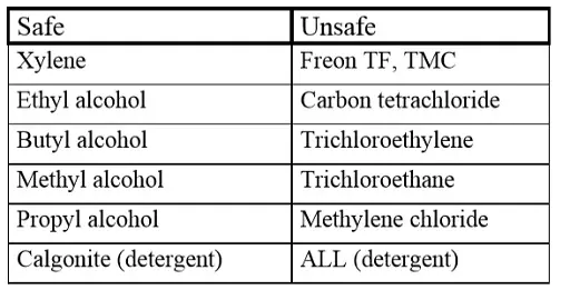
Cleaning agents and other contaminants can penetrate seals and promote internal corrosion. Halogen-containing substances are a particular concern. Solvent name alone is not enough to establish compatibility: concentration, temperature, exposure time, drying, seal material and the capacitor series all matter. [1]
Use only the cleaning, soldering, coating and adhesive processes approved for the selected product. Do not apply a general cleaning-bath temperature rule in place of manufacturer instructions. Surface-mount parts must be checked against their permitted reflow profile and number of reflow exposures.
Failure modes
Gradual electrolyte loss is an important wear-out mechanism in wet aluminum electrolytic capacitors. It commonly causes increasing ESR and changes in capacitance, but the exact progression depends on construction and operating conditions. End of useful life is determined by specified parameter limits, not by the assumption that every dried capacitor becomes a simple resistor. [1]
Other failure modes include dielectric breakdown, excessive leakage, internal connection failure, electrolyte leakage and vent operation. Electrical overstress, reverse polarity, overheating, contamination, vibration and mechanical damage can cause failures before normal wear-out.
Inspection should therefore combine capacitance and ESR or impedance measurements with leakage testing where appropriate. Interpret results using the specified measurement conditions. Visual inspection alone cannot establish remaining useful life, and normal external appearance does not exclude significant electrical degradation.
The following legacy summary is retained for comparison with the original article. Its historical ranges and generalisations do not replace current series specifications.
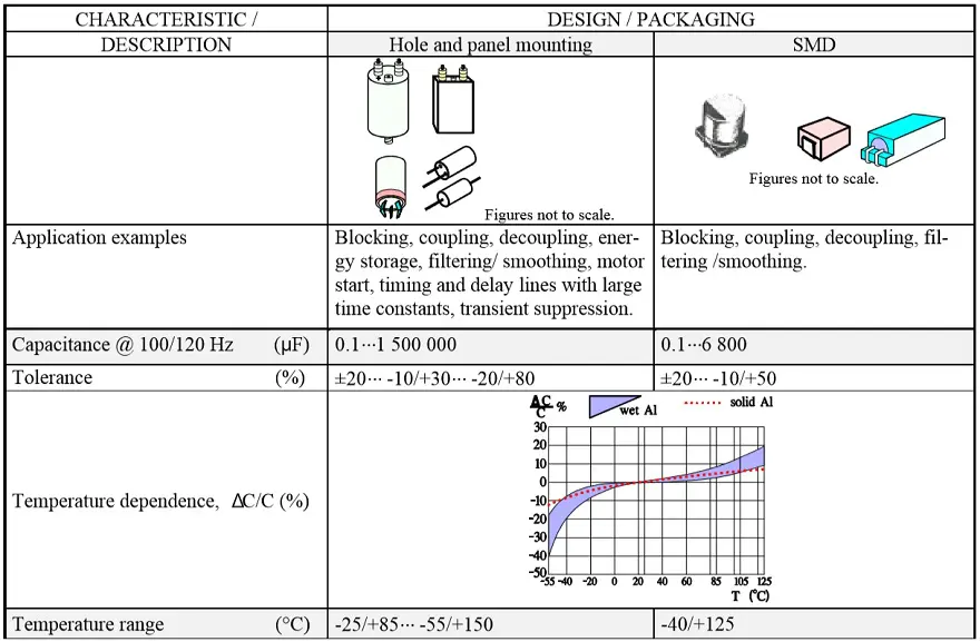

Legacy lifetime calculation graphic
The original lifetime calculation graphic is retained alongside the worked example in Eq. (7). For design calculations, use the defined temperature basis and limitations discussed above rather than treating a graphical example as a product specification.

Solid Aluminum Electrolytic Capacitors, Polymer, Hybrid and TCNQ Salt
Solid conductive polymer capacitors and hybrid capacitors address different limitations of conventional wet constructions. Historical organic semiconductor salt types are also relevant when identifying components in older equipment. These technologies share an aluminum oxide dielectric, but their electrolyte conductivity, ageing mechanisms and application requirements differ.
Conductive polymer aluminum electrolytic capacitors
In a solid polymer aluminum electrolytic capacitor, a conductive polymer contacts the aluminum oxide dielectric on an etched and formed anode. Its relatively high conductivity reduces the electrolyte contribution to ESR. Compared with many conventional wet capacitors, this gives lower impedance in the relevant frequency range and less variation of ESR with temperature. The magnitude of the improvement depends on the products and measurement conditions being compared. [3, 4]
Solid polymer does not mean zero ESR, temperature-independent performance or unlimited life. Conductive paths, contacts, dielectric losses and terminal inductance remain important. Polymer conductivity and the surrounding materials can also change with prolonged thermal or environmental exposure. Temperature, humidity and voltage requirements must therefore be assessed using the selected series documentation. [4]
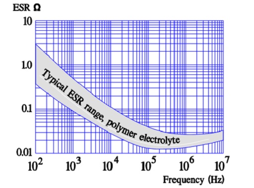
Available voltage, capacitance, ESR and operating-temperature ranges depend on the series and package. Current product families extend beyond the voltage and temperature limits associated with early polymer capacitors. Do not apply an old technology-wide range or a universal percentage voltage derating to a current part. Check the maximum permitted operating voltage, any temperature-dependent voltage reduction, ripple limits and transient restrictions in its datasheet. [3]
Polymer aluminum capacitors are polarized. Unless the manufacturer explicitly specifies otherwise for the exact product, design the circuit so that reverse voltage does not occur. A local defect-isolation mechanism does not authorise operation beyond rated voltage and does not eliminate the possibility of a short-circuit failure.
Stacked chip construction and current paths
Solid polymer aluminum capacitors are available in wound can constructions and stacked chip constructions. In a representative stacked design, etched and anodically formed aluminum elements carry a conductive polymer layer over the dielectric. Carbon and silver-containing layers provide the cathode connection, and the connected elements are enclosed in a moulded resin package. Figures 22 and 23 illustrate this construction. [4]
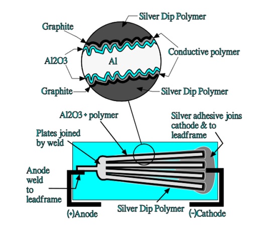

The electrical benefit comes from contacting a large dielectric surface through conductive layers and short collection paths. Parallel elements and suitable terminal geometry can reduce resistance and inductance. However, the resistance through the polymer, the contact layers and the package connections all contribute to the measured terminal behaviour.
A simple description of current flowing vertically in aluminum and horizontally in tantalum is not a general comparison between the technologies. Tantalum capacitors can also use conductive polymer, and construction varies within each family. Compare actual ESR, impedance, equivalent series inductance and package geometry rather than inferring performance from the anode material alone.
Low-ESR polymer capacitors are useful for smoothing, converter output filtering and local energy buffering. In a regulated supply, confirm that the proposed capacitance and ESR fall within the controller’s stability requirements. Replacing an older wet capacitor with a much lower-ESR part is an electrical design change, not merely a mechanical substitution.
For mechanically demanding equipment, evaluate the complete mounting arrangement, including package attachment, board bending, vibration and shock. A low electrical ESR does not establish mechanical suitability.
Hybrid aluminum electrolytic capacitors
Hybrid aluminum electrolytic capacitors combine conductive polymer with liquid electrolyte. The polymer provides a low-resistance conduction path, while the liquid electrolyte supports electrochemical oxide repair. The combination can provide low ESR and useful ripple-current capability without adopting all the characteristics of a fully solid construction.
Hybrid capacitors remain liquid-containing devices. They must therefore be evaluated for electrolyte retention, sealing, temperature-dependent ageing and the manufacturer’s useful-life model. Neither the wet-capacitor approximation in Eq. (6) nor a life model for a fully solid polymer capacitor should be transferred automatically to a hybrid series.
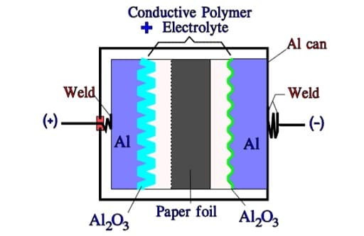
Temperature capability has expanded beyond the limits described in early hybrid overviews. For example, Panasonic’s ZF-series leaflet specifies an operating range from −55 °C to 150 °C and an endurance rating of 1,000 h at 150 °C. These values apply to that series and its stated test conditions; they are not general limits or service-life predictions for hybrid capacitors. [5]
Compare hybrid candidates using leakage current, ESR, ripple-current rating at the relevant temperature, endurance conditions, humidity requirements and available vibration-resistant constructions. Do not assume that every hybrid capacitor tolerates a more severe reflow profile than every solid polymer capacitor. Assembly compatibility must be established for the exact package and series.
TCNQ salt aluminum electrolytic capacitors
Historical organic semiconductor aluminum capacitors used a conductive salt based on TCNQ, tetracyanoquinodimethane. In this construction, the wound element was impregnated with the electrolyte material at elevated temperature, and the electrolyte became solid on cooling. This is distinct from both liquid electrolyte and conductive polymer construction.
These capacitors helped establish low-ESR solid aluminum technology. However, a historical trade name is not a sufficient way to identify the electrolyte in a replacement component. Current OS-CON products are described as aluminum conductive polymer capacitors, so the OS-CON name must not be treated as proof of TCNQ chemistry. [3]
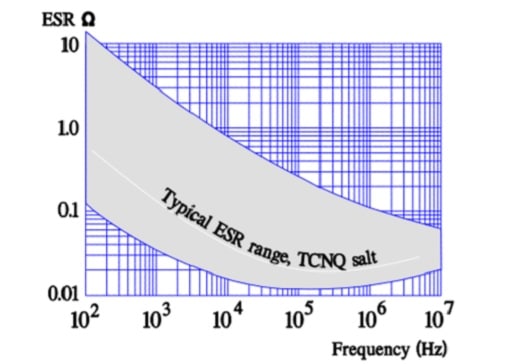
For maintenance of legacy equipment, identify the original manufacturer, series and full part number before selecting an alternative. Compare voltage, capacitance, impedance, leakage current, temperature range, dimensions, polarity and assembly requirements. Mechanical handling and soldering restrictions from the original specification remain relevant to unused legacy stock.
Do not transfer historical capacitance ranges, maximum voltages, temperature-dependent derating rules or surge restrictions to a modern polymer replacement. Conversely, the performance of a modern polymer capacitor does not establish the suitability of an old organic semiconductor part.
The following legacy summary is retained to support comparison with older component descriptions. Current procurement and design decisions require the documentation for the actual product supplied.
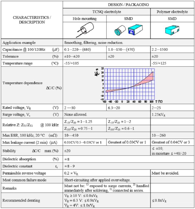
Historical Solid Aluminum Capacitors with Manganese Dioxide
Solid aluminum capacitors using manganese dioxide, commonly identified in older literature as SAL capacitors, are a separate historical construction. Their characteristics should not be confused with those of current conductive polymer aluminum capacitors. This section retains the original technology overview and graphics for legacy-equipment identification.
Construction and operating characteristics
These capacitors use an etched aluminum anode, an aluminum oxide dielectric and a solid semiconducting manganese dioxide cathode material. The manganese dioxide is deposited through a thermal conversion process. Carbon and silver-containing layers provide the connection between the solid electrolyte and the external cathode termination.
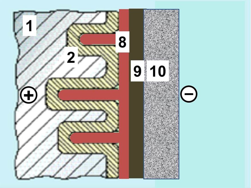
Historical products included resin-coated radial constructions and axial can constructions. Their solid electrolyte avoids liquid-electrolyte dry-out, but this does not imply unlimited life or immunity to storage conditions, mechanical damage, dielectric defects or electrical overstress.
The solid electrolyte and its contact with the etched anode influence capacitance utilisation, ESR and stability. Formation margins, temperature ratings and pulse capability belong to the particular construction. Historical prices and rating ranges are not useful universal selection rules for present-day capacitor technology.
Temperature and frequency characteristics
Figures 27 to 31 preserve the original illustrative characteristics. They show how the historical solid construction differs from conventional wet capacitors, but normalised curves do not define the limits of an unidentified legacy component. Use the original series datasheet when restoring equipment or assessing existing stock.
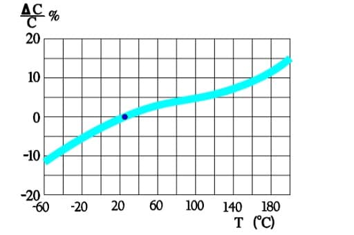
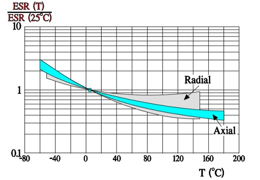
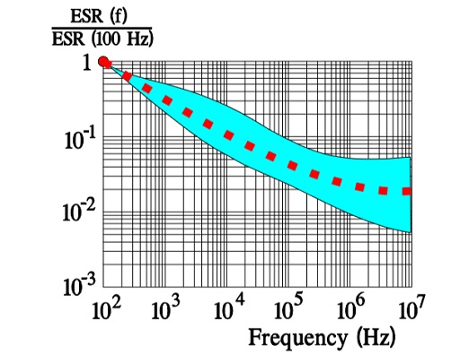
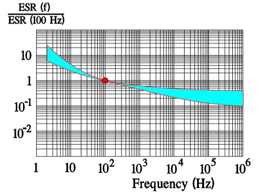
Package and terminal geometry contribute to high-frequency impedance. A radial or stacked construction may offer a different inductance from an axial wound construction, but lead style alone is not a sufficient basis for assigning a numerical ESL or maximum useful frequency.
Reverse voltage, mechanical handling and replacement
Any reverse-voltage capability specified for a historical SAL series applies only under its stated conditions. It must not be extended to other solid aluminum capacitors, conductive polymer products or wet constructions. A capacitor’s polarity marking and product specification take precedence over a general technology description.
Mechanical forces applied to the leads can damage resin-coated parts or their internal connections. Support the component during lead forming and avoid transmitting board or assembly stress into the body. For a replacement, assess the fault energy available from the circuit as well as capacitance and voltage; solid electrolyte does not establish that all overstress failures will be benign.

Design and Selection Checklist
Select the capacitor from the application waveform, thermal environment and required service interval rather than from nominal capacitance alone. The following checks apply primarily to power-supply filtering and energy storage; signal and timing circuits need additional attention to leakage, dielectric absorption and low-frequency behaviour. [1, 2, 4]
Electrical requirements
- Define the minimum required capacitance after initial tolerance, operating temperature, frequency and permitted ageing have been considered.
- Check the maximum instantaneous terminal voltage, including DC bias, ripple, start-up overshoot, shutdown behaviour and external transients. Apply the product’s temperature-dependent voltage requirements.
- Confirm polarity throughout the operating cycle. Use a specifically suitable non-polar construction or another technology when voltage reversal is required.
- Compare ESR and impedance at the application frequencies and temperatures. Do not compare a typical ESR value with another supplier’s guaranteed maximum as though they were equivalent.
- Calculate or measure the ripple-current spectrum. Apply only the frequency and temperature corrections specified for the selected series.
- Check peak current, repetitive charge-discharge duty and transient energy separately from the continuous RMS ripple-current rating.
- For converter output capacitors, verify the controller’s permitted capacitance and ESR range and validate the resulting transient response and stability.
- For series banks, assess transient and steady-state voltage sharing, balancing losses and discharge arrangements. For parallel banks, check current sharing, interconnect impedance and thermal uniformity.
Thermal conditions, life and measurement
- Use the local temperature at the capacitor, not a remote enclosure or room-temperature reading.
- Include self-heating and adjacent heat sources. Use manufacturer thermal data or an approved life calculator where available, and validate the assembled equipment under representative worst-case conditions.
- Distinguish endurance testing, shelf-life testing, estimated useful life and statistical reliability. These describe different aspects of performance.
- State the capacitance and ESR measurement frequency, temperature, test amplitude and equivalent-circuit mode. Account for fixture and lead effects where low impedance is being measured.
- Measure leakage with the specified conditioning, voltage, temperature, current limitation and elapsed time. Do not compare an immediate charging-current reading with a settled leakage-current limit.
Assembly, storage and qualification
- Confirm dimensions, terminal arrangement, polarity marking, land pattern or hole pattern, mounting support and pressure-relief clearance.
- Review the permitted soldering profile, number of thermal exposures, cleaning chemistry, coating and adhesive compatibility. Follow any dry-pack, floor-life and moisture-handling requirements applicable to the package.
- Specify the actual vibration, shock, thermal cycling, humidity and atmospheric conditions. Compare the complete qualification test conditions, not merely a headline acceleration or temperature value.
- Check storage conditions, date codes, solderability and leakage requirements before using older stock. Apply reforming only when required and according to the manufacturer’s procedure; reforming does not restore electrolyte already lost through ageing.
- For safety-related equipment, assess short-circuit and open-circuit consequences, fault-current limitation, pressure relief, insulation and safe discharge. A component qualification does not replace equipment-level safety assessment.
Catalog parts versus custom constructions
A catalog part is appropriate when its published ratings, qualification evidence and assembly limits cover the application. Prefer a documented, traceable series over an apparently interchangeable part whose thermal, ripple or mechanical limits are unclear. For an approved alternative, compare the complete specification rather than only capacitance, voltage and case size.
Consult the manufacturer when the application involves unusual pulse duty, high peak current, large voltage swings, restricted cooling, severe vibration, special mounting or a required lifetime outside the catalog model. Customisation can involve connections, internal construction, sealing or thermal design rather than simply a different marking. Agree the electrical limits, test methods, acceptance criteria and change-control requirements in writing. [1]
Conclusion
Aluminum electrolytic capacitor selection is a balance between capacitance, voltage, loss, temperature, life and construction. Wet types remain useful for economical bulk storage and filtering, while conductive polymer and hybrid types provide additional options where impedance, ripple current or temperature performance drives the design.
The decisive information is the specification of the selected series under the intended operating conditions. Verify the complete voltage waveform, ripple spectrum, thermal environment and assembly process, and validate the resulting performance in the equipment. Historical technology summaries and simplified lifetime rules are useful for understanding mechanisms, but they are not substitutes for product-specific limits.
FAQ
These answers summarise the main construction, selection and maintenance questions. Product-specific datasheets take precedence over general descriptions of a capacitor technology.
An aluminum electrolytic capacitor uses a thin aluminum oxide dielectric formed on an etched aluminum anode. An electrolyte contacts the oxide and forms part of the cathode system. The large effective surface and thin dielectric provide high capacitance in a compact package. Most types are polarized and are used for filtering, smoothing and energy storage.
Wet types use liquid electrolyte, solid polymer types use a conductive polymer, and hybrid types combine polymer with liquid electrolyte. Polymer generally reduces the electrolyte contribution to ESR. Hybrid construction also retains liquid-supported oxide repair. Selection must still consider the actual voltage, temperature, leakage, ripple and lifetime specifications rather than assuming that one technology is always superior.
Do not treat reverse voltage as an allowable operating condition unless the exact product specification explicitly permits it. Polarized aluminum electrolytic capacitors can be damaged by electrochemical reactions, excessive leakage, heating and gas generation. Check the full terminal waveform during normal operation, start-up and shutdown. Use a suitable non-polar construction or another technology when reversal is required.
Ripple current produces resistive loss proportional to its RMS value squared and the ESR at the relevant frequency and temperature. This loss raises the internal temperature and can accelerate ageing. For a waveform containing several frequency components, assess their combined heating contribution. Use the selected series ripple ratings, correction factors and thermal or lifetime model.
No. Doubling estimated life for each 10 °C reduction is a commonly used approximation for wet aluminum electrolytic capacitors within defined limits. The relevant temperature basis and permitted extrapolation depend on the manufacturer. Ripple heating, voltage, construction and environmental exposure can also matter. Do not automatically apply the same relationship to polymer and hybrid products.
Not solely because capacitance, voltage and dimensions match. Compare leakage, impedance, ripple capability, temperature limits, assembly requirements and the required service interval. In converter outputs, a substantial ESR change can affect regulator behaviour. Confirm the controller requirements and validate the circuit. Also check polarity, terminal geometry, fault protection and any mechanical qualification requirements.
Equal nominal capacitance does not ensure equal steady-state voltage because leakage currents differ between capacitors. Balancing resistors or an appropriate active circuit may be required to keep each capacitor within its voltage limit. Transient sharing also depends on capacitance and circuit impedance. Check resistor tolerance, working voltage, dissipation and the separate requirement for safe discharge.
Check the manufacturer’s storage requirements, date code, physical condition, solderability and electrical limits before use. Long storage can increase initial leakage, but the required conditioning procedure depends on the product. Reforming must follow manufacturer instructions and does not replace electrolyte lost through ageing. Unidentified legacy stock should not be approved from a capacitance measurement alone.
How to Select an Aluminum Electrolytic Capacitor
Use this procedure to select a candidate and then validate it in the intended equipment. Keep the operating assumptions and the product revision with the design record so that later substitutions can be assessed against the same requirements.
Select and validate an aluminum electrolytic capacitor using the application waveform, electrical limits, thermal conditions and assembly requirements.
- Define the application and waveform
Identify the filtering, energy-storage, coupling or timing function. Establish the minimum required capacitance and the complete terminal-voltage waveform, including ripple, start-up, shutdown and transients.
- Choose the construction and voltage rating
Compare wet, solid polymer and hybrid candidates. Check polarity, maximum operating voltage and any temperature-dependent restrictions in the exact series datasheet. Do not use surge voltage as a continuous rating.
- Check capacitance, impedance and ripple current
Allow for capacitance tolerance and operating variation. Evaluate ESR and impedance over the relevant frequencies and temperatures. Apply the specified ripple-current corrections and check separate pulse or repetitive charge-discharge limits.
- Assess thermal conditions and useful life
Determine the local ambient temperature and include self-heating and nearby heat sources. Use the manufacturer’s thermal and lifetime methods within their stated limits. Distinguish endurance-test duration from an estimated equipment service interval.
- Confirm assembly and safety requirements
Verify dimensions, terminations, mounting support, vent clearance, soldering and cleaning compatibility. Review storage, humidity, vibration and shock requirements. Provide suitable fault protection, insulation and safe discharge arrangements.
- Validate the selected part in the equipment
Measure representative operating waveforms and temperatures, including worst-case conditions. Confirm converter stability where relevant. Record the approved manufacturer, series, part number and specification revision, and reassess alternatives against the complete requirements.
Further Reading
The following articles expand the underlying mechanisms and application methods discussed here.
- Electrolytic Capacitors: background on oxide dielectrics, electrolyte systems and electrode construction.
- DCL Leakage Current and Insulation Resistance: definitions and measurement considerations for leakage and insulation behaviour.
- Ripple Current and its Effects on the Performance of Capacitors: background on ripple-current loss and internal heating across capacitor technologies.
- Estimating and Modelling Lifetime of Aluminum Electrolytic Capacitors for any Ripple Current and Temperature: a video explanation of temperature, ripple current and lifetime modelling.
References
Numbered citations identify the technical documents used for the corresponding construction, measurement and application guidance. Individual product datasheets take precedence over general application guides.
- Cornell Dubilier / Knowles, Aluminum Electrolytic Capacitor Application Guide, manufacturer application guide, revision R2, publication year not stated.
- Arne Albertsen, Jianghai Europe Electronic Components GmbH, Electrolytic Capacitor Leakage Current, Jianghai Europe, 2018.
- Panasonic Industry / Mouser Electronics, OS-CON Aluminum-Polymer Solid Capacitors, product-family overview, updated 2026.
- Cornell Dubilier, Application Guide, Solid Polymer Aluminum SMT Capacitors, manufacturer application guide, publication year not stated.
- Panasonic Industry Europe GmbH, Conductive Polymer Hybrid Aluminum Electrolytic Capacitors: ZF-Series, manufacturer product leaflet, publication year not stated.
Latest technical review and revision: 27 October 2026. Updated technology descriptions, measurement and selection guidance, lifetime examples and references; retained historical graphics for comparison and legacy-equipment identification.