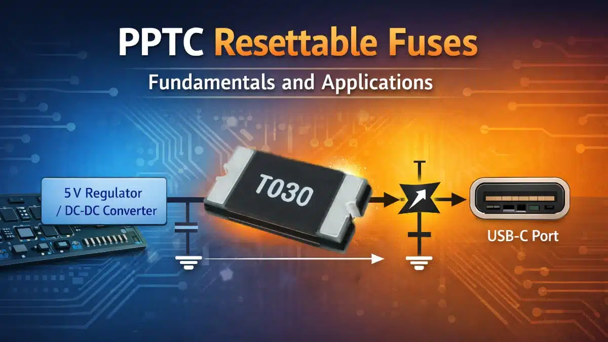
This article presents a practical guide to polymer PTC (PPTC) resettable fuses for board-level overcurrent protection in electronic systems.
Key Takeaways
- PPTC resettable fuses provide reusable overcurrent and overtemperature protection for low-voltage electronics.
- Unlike traditional fuses, PPTCs automatically reset after cooling, allowing for maintenance-free operation.
- Key selection parameters include hold current, trip current, and thermal characteristics, which influence performance under real conditions.
- Designers should consider thermal management and potential limitations of PPTCs to avoid common pitfalls.
- PPTCs are ideal for applications like USB ports and battery packs where automatic recovery is essential.
1. Introduction
Polymer positive temperature coefficient devices, commonly called PPTC resettable fuses, provide reusable overcurrent and overtemperature protection for low-voltage electronic circuits.
Unlike one-shot fuses, they transition from a low-resistance state to a high-resistance state during a fault and can automatically return to operation after the fault is removed and the device cools down. This application note explains the operating principle, key datasheet parameters, selection method, thermal considerations, and common use cases relevant to design engineers.
PPTC devices are widely used where maintenance-free protection is preferred over fuse replacement, especially in battery-powered equipment, industrial control boards, consumer electronics, and I/O interfaces. Their appeal comes from compact size, self-resetting behavior, and compatibility with radial and SMD assembly flows, including dense SMT layouts. In practical circuit design, however, a PPTC must be treated as a thermally controlled nonlinear resistor rather than as a direct one-for-one replacement for a melting-wire fuse.
2. What Is a PPTC Fuse?
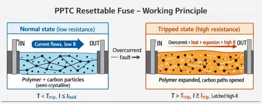
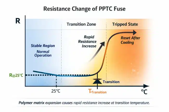
A PPTC resettable fuse is a passive protection component based on a conductive polymer composite loaded with carbon particles. Under normal conditions, the conductive network inside the polymer provides a low-resistance current path. When excessive current causes self-heating, the polymer expands, conductive paths separate, and the resistance rises sharply, limiting current to a low residual value.
This behavior gives the designer a reusable protection element for overloads, wiring faults, and accidental shorts on low-voltage DC rails. Because the device does not fully open the circuit in the tripped state, it should be considered a current-limiting protector rather than a true galvanic disconnect element.
3. Operating Principle
At room temperature, the polymer matrix is in a state that keeps conductive carbon chains close enough together for current to pass with relatively low resistance. When the current exceeds the device’s thermal balance, internal heating raises the material temperature until the polymer expands and disrupts the conductive network. Resistance then increases by several orders of magnitude, sharply reducing current and power delivered to the faulted circuit.
The device remains in its tripped high-resistance state while voltage is applied and enough heat is generated to sustain that state. After power is removed or the fault current falls sufficiently, the device cools and returns toward its low-resistance state, enabling automatic reset. Repeated trip events can increase the stabilized low-state resistance over life, so end-of-life resistance must be considered in tight voltage-drop budgets.
4. Core Datasheet Parameters
The most important electrical ratings for PPTC selection are hold current, trip current, maximum voltage, maximum interrupt current, initial resistance, and time-to-trip behavior.
| Parameter | Meaning for design | Why it matters |
|---|---|---|
| Hold current | Maximum current carried without tripping at stated ambient temperature. | Must exceed worst-case steady-state load current with temperature margin. |
| Trip current | Minimum current that causes reliable transition to the tripped state. | Must stay below the expected fault current so protection activates. |
| Maximum voltage | Highest voltage the device can withstand safely. | Must exceed the maximum applied circuit voltage during fault conditions. |
| Maximum interrupt current | Highest fault current the device can safely tolerate. | Prevents device overstress under supply short-circuit conditions. |
| Initial resistance | Resistance before tripping, usually specified at 25 °C. | Defines nominal voltage drop and power loss in normal use. |
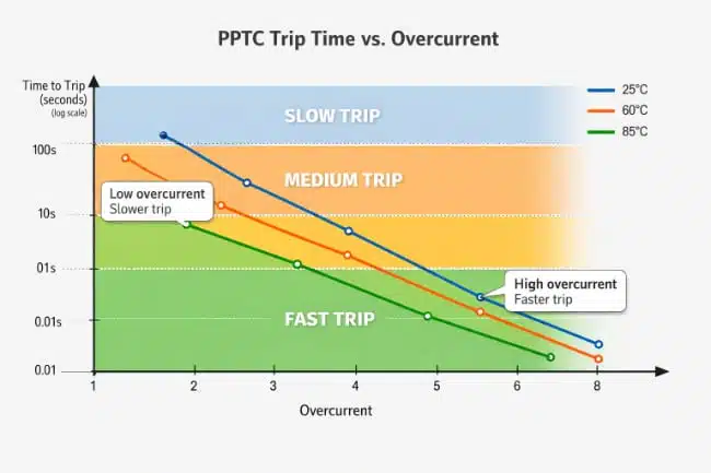
| Time to trip | Time needed to enter high-resistance state at a given overcurrent. | Determines whether downstream circuits survive before protection reacts. |
Temperature derating curves are equally important because hold current decreases as ambient temperature rises. A part that appears correct at 25 °C may nuisance-trip in a sealed enclosure, near a hot regulator, or on a copper-poor PCB at elevated ambient.
5. How PPTCs Differ from Traditional Fuses
Traditional fuses interrupt a fault by permanently melting a metallic element, while PPTCs shift into a reversible high-resistance state through a thermal phase change in polymer material. This means PPTCs avoid replacement after intermittent faults, but they also allow some residual leakage current and do not provide the same clear disconnect behavior as one-shot fuses.
| Attribute | PPTC resettable fuse | Traditional fuse |
|---|---|---|
| Fault response | Current limiting through sharp resistance increase. | Current interruption through element melting. |
| Reset behavior | Automatic after cooling and fault removal. | Requires replacement. |
| Normal-state loss | Low but non-zero resistance. | Usually negligible until fuse opens. |
| Circuit disconnection | Partial, not a full open circuit in most cases. | Full open circuit after operation. |
| Best fit | Repetitive field faults, inaccessible equipment, user ports. | Safety isolation, higher fault energy, clear fail-safe disconnect. |
For many board-level designs, the real decision is not which technology is universally better, but which failure mode is more acceptable in the end product. PPTCs are strongest in convenience and serviceability, while classic fuses remain stronger for hard isolation and defined safety clearing behavior.
Safety and standards considerations
PPTC resettable fuses are typically used as secondary overcurrent protection elements and are not a drop‑in replacement for primary, safety‑critical fuses required by product safety standards. In many applications the PPTC is used in combination with a traditional fuse or circuit breaker that provides defined, non‑resettable interruption under worst‑case fault conditions. Depending on the end‑equipment category, applicable standards such as IEC 62368‑1, IEC 60950‑1 (legacy IT), or automotive standards may specify the type of primary protective devices and clearances, while PPTCs are treated as supplemental components used to limit fault currents, improve robustness of interfaces, and reduce service interventions.
Designers should therefore check whether their safety standard allows self‑resetting devices for a given protection function and, if necessary, employ PPTCs only as additional protection alongside approved fuses, breakers, or polyswitches that carry the appropriate agency recognitions.
6. Main Application Areas
Modern PPTC portfolios target both through-hole and SMD assembly, with current ratings spanning signal-level protection to several amperes on power rails. Typical manufacturer family, includes radial types covering 0.05 A to 5 A and voltage ratings up to 72 V depending on part type.
Common applications include:
- Battery packs and BMS sense or distribution lines.
- Secondary-side protection in DC power supplies and adapters.
- Industrial controllers, I/O modules, and sensor interfaces exposed to field wiring faults.
- USB, charging, audio, and accessory ports in consumer electronics and wearables.
- Dense storage and SSD electronics where resettable protection saves service effort and board area.
These use cases share one theme: the designer wants fault tolerance and automatic recovery without field replacement of a blown fuse.
7. Selection Method
A practical selection flow starts with maximum continuous current at the highest real operating temperature, not with nominal room-temperature load current. The selected hold current should exceed the worst-case steady-state load with enough margin to avoid nuisance tripping under tolerance, startup transients, and elevated ambient conditions.
Next, the trip current must remain below the minimum credible fault current so the device will actually transition under the defined fault case. This is particularly important with current-limited supplies, foldback converters, or battery-powered systems that may not deliver a large short-circuit current.
The designer should then verify three additional constraints:
- The device maximum voltage must exceed the highest applied fault voltage.
- The maximum interrupt current must exceed the available short-circuit current from the source.
- The time-to-trip curve must be compatible with the thermal survival of semiconductors, PCB traces, connectors, and cables downstream.
8. Thermal and Layout Considerations
PPTC performance is strongly coupled to thermal environment, so the same part number can behave differently across board layouts and enclosures. Large copper pours, forced airflow, and heat spreading into the PCB can delay tripping, while nearby hot components can lower the effective hold current and promote nuisance operation.
Useful layout rules include:
- Avoid placing the PPTC directly next to hot power semiconductors, transformers, or wirewound resistors.
- Review manufacturer guidance on copper area because excessive heat sinking can change trip behavior.
- Validate trip and reset behavior on the final PCB, not only on a schematic-level assumption.
- Recheck voltage drop at end-of-life resistance, especially on 3.3 V and 5 V rails with tight regulation margins.
In compact SMT products, the thermal interaction between the PPTC and the surrounding copper often determines whether the design behaves robustly or unpredictably.
9. Limitations and Design Pitfalls
PPTCs do not replace surge suppressors, ESD diodes, or safety-certified mains protection devices. They are best at overload and sustained short-circuit limitation, not at absorbing fast high-energy voltage transients.
Common design mistakes include selecting only by rated current, ignoring high-ambient derating, assuming complete circuit disconnection after trip, and forgetting long-term resistance drift. Another recurring issue is pairing a PPTC with a source that current-limits below the device’s effective trip threshold, leaving the protector hot but not fully transitioned.
Long‑term stability and resistance drift
PPTC devices exhibit irreversible changes of resistance over their lifetime as a result of repeated trip/reset cycles and prolonged operation close to their hold current. Each trip event slightly increases the room‑temperature resistance, and this drift accumulates over time. Manufacturers typically specify the maximum allowed resistance change after a defined number of trip cycles and after storage at elevated temperature, giving the designer a guideline for worst‑case end‑of‑life performance.
In practice, this means that design margins for voltage drop and power dissipation should be evaluated not only at initial resistance but also at the specified end‑of‑life resistance values. Applications with very tight loss budgets or high cycle counts (for example, frequently shorted ports in harsh environments) may require a higher‑current PPTC type or alternative protection concepts to maintain acceptable performance throughout the service life.
10. Example Use Case: USB or Accessory Port Protection
A low-voltage user-accessible port is a classic PPTC application because cable faults and accidental shorts are common, while field service should be avoided. In this role, the PPTC is placed in series with the supply path so that a short at the connector drives the device into its high-resistance state and reduces current stress on the upstream regulator or switch.
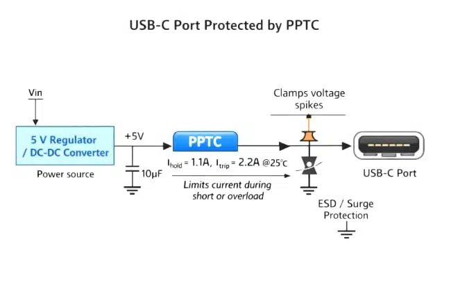
For this type of design, engineers typically check nominal port current, hot-plug surge profile, source current limit, voltage drop at full load, and reset behavior after fault removal. The result is a user-friendly protection scheme that can recover automatically after cable replacement or power cycling.
Design example: PPTC selection for a 5 V, 3 A USB port
For a 5 V USB port with a nominal continuous load of 3 A and a downstream overcurrent‑limited power switch, the PPTC must carry the normal load without nuisance tripping while still reacting quickly to hard shorts on the connector. A typical dimensioning flow can look like this:
- Step 1 – Define continuous current and ambient:
Assume continuous load current A and maximum ambient temperature . The PPTC hold current at 40 °C must exceed the maximum continuous current with reasonable margin. - Step 2 – Choose and
A common guideline is to target . For 3 A this points to a device with around 3.75 A at the operating temperature. The trip current should be comfortably above the maximum expected inrush or transient load but below the upstream current limit. For example, if the upstream switch limits at 6 A, a PPTC with A provides a practical compromise. - Step 3 – Check voltage and surge capability:
For a 5 V USB rail, a PPTC with a maximum rated voltage to 9 V is sufficient, provided it can withstand the fault current until the upstream protection reacts. The maximum fault current rating of the PPTC must be equal to or higher than the short‑circuit current of the source or the current limit of the upstream switch, whichever is lower. - Step 4 – Verify time‑to‑trip:
Time‑to‑trip curves in the datasheet should be checked at the expected fault current level. If a 5 A fault current is expected, the time‑to‑trip at this current should be short enough to protect connector pins and PCB traces and to avoid long thermal stress on neighboring components, while still allowing brief plug‑in transients. - Step 5 – Check resistance and power dissipation:
Finally, verify that the initial resistance of the selected PPTC does not cause unacceptable voltage drop at 3 A and that its I²R losses at maximum load are acceptable at the worst‑case ambient temperature. This step is particularly important in high‑current USB‑C applications where total channel voltage budget is tight.
11. Product Family Positioning
The current market direction includes PPTC portfolios in both radial and SMD formats, optimized for compact electronics and automated assembly. Compact SMD types aim dense boards in consumer, wearable, and storage applications.
This product segmentation also reflects a broader engineering need: one technology platform that can cover low-current signal protection, DC rail protection, and battery-related applications while fitting different manufacturing flows.
12. Conclusion
PPTC resettable fuses are a highly practical board-level protection option for low-voltage electronics when automatic recovery, reduced maintenance, and compact integration are valued. Their correct use depends less on headline current rating and more on thermal design, derating, time-to-trip behavior, source fault capability, and acceptable residual current in the tripped state.
For design engineers, the most effective mindset is to treat the PPTC as a thermally driven protection element that must be validated in-circuit under worst-case ambient and fault conditions. Used that way, PPTCs can significantly improve robustness of ports, battery lines, and low-voltage power rails without the service penalty of traditional one-shot fuses.
FAQ
A PPTC resettable fuse is a polymer positive temperature coefficient (PTC) device used for board‑level overcurrent protection in low‑voltage circuits. At normal temperature it has low resistance, but when excessive current causes self‑heating, the polymer expands, carbon conduction paths break, and the resistance rises sharply, which limits current to a safe level until the device cools and resets.
PPTCs are ideal where automatic reset and maintenance‑free operation are more important than a hard, single‑shot disconnection, for example in USB ports, battery packs, and field‑wired I/O modules that are hard to service. Traditional fuses are still preferred for primary safety protection, high fault energy, and applications that require a clearly defined open‑circuit failure mode under safety standards.
The key parameters are hold current , trip current , maximum voltage , maximum interrupt current , initial resistance, and time‑to‑trip performance. Designers also need to pay close attention to temperature derating curves, because and change significantly with ambient temperature and mounting conditions.
No. A PPTC is not a surge arrester and does not replace TVS diodes, MOVs, or gas discharge tubes for transient overvoltage protection. It also is not intended to replace safety‑certified primary fuses on mains‑voltage inputs; instead, PPTCs are best used as secondary, board‑level protection on low‑voltage rails.
Nuisance tripping is often caused by higher real ambient temperature, nearby hot components, or large copper areas changing the device’s thermal behavior compared with the bench setup. In the final enclosure, the effective hold current can be lower than the datasheet 25 °C value, so a PPTC that seemed fine in early tests may trip under worst‑case conditions.
No. In the tripped state the PPTC moves to a high‑resistance condition but still passes a small leakage current, so the circuit is current‑limited rather than fully open. For applications that require a guaranteed galvanic isolation after a fault, a traditional fuse or breaker is still required upstream.
How to select a PPTC resettable fuse for your circuit
- Step 1 – Define operating and fault conditions
Determine nominal supply voltage, maximum continuous load current, and the highest expected ambient temperature in the end product. Identify credible fault cases such as hard short to ground, wiring errors, or downstream regulator failure, and estimate the available short‑circuit current from the source.
- Step 2 – Choose hold current
Select a PPTC whose hold current at the relevant ambient temperature is comfortably above the worst‑case steady‑state load current (typically 25–40% margin). Use the datasheet derating curve to adjust for high ambient temperature and limited airflow so the device does not nuisance‑trip in normal operation.
- Step 3 – Verify trip current
Check that the PPTC’s trip current is below the minimum fault current so that the device will reliably enter its high‑resistance state for all defined fault scenarios.
Be especially careful with current‑limited supplies or foldback converters, where the available fault current may be barely above . - Step 4 – Check voltage and interrupt ratings
Ensure the maximum voltage of the device is higher than the worst‑case voltage that can appear across it during a fault, including any transients seen on the rail. Confirm that the maximum interrupt current exceeds the supply’s prospective short‑circuit current at that voltage so the PPTC can safely clear the fault.
- Step 5 – Evaluate time‑to‑trip curves
Use the datasheet time‑to‑trip versus overcurrent curves at the relevant ambient temperature to estimate how long the PPTC takes to trip for each fault case. Verify that downstream components, PCB traces, and connectors can survive the I²t energy during that time without overheating or damage.
- Step 6 – Consider resistance and voltage drop
Calculate worst‑case voltage drop across the PPTC at nominal current using the maximum initial or post‑trip resistance values. Check that the remaining voltage at the load still meets regulation limits, especially on 3.3 V and 5 V rails and on USB or other standardized interfaces.
- Step 7 – Validate in the real thermal environment
Place the chosen PPTC on the actual PCB near its final neighbors and run tests at worst‑case ambient temperature and enclosure conditions. Perform repeated fault and reset cycles to observe trip behavior, reset time, and resistance drift over life, and adjust the part or layout if nuisance tripping or excessive heating occurs.