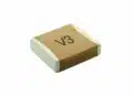

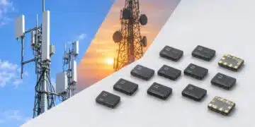



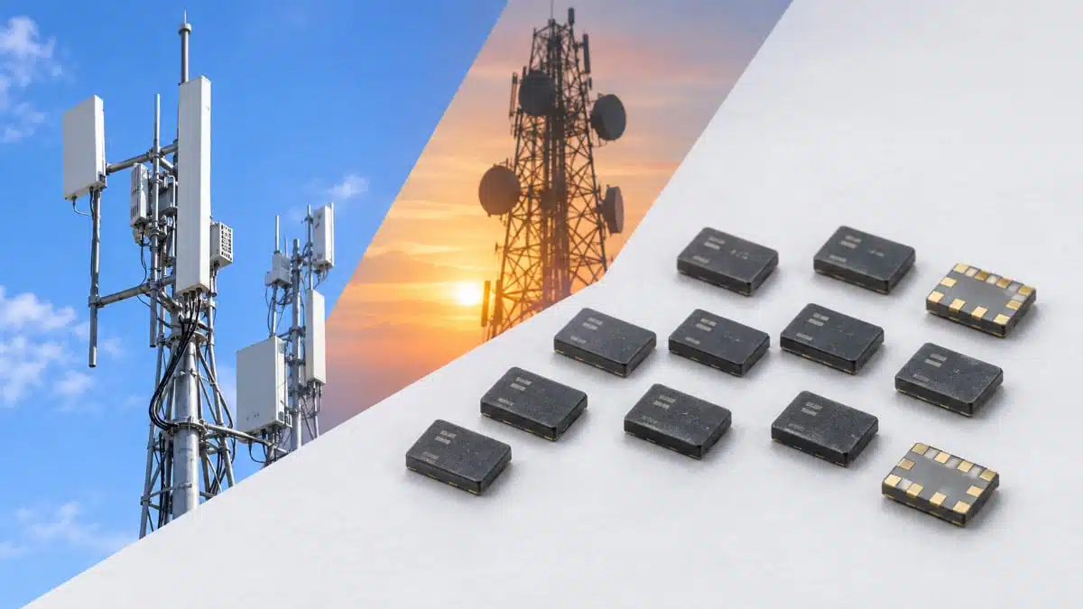
Kyocera has expanded its base-station SAW filter lineup alongside its mass-produced SAW duplexers, using temperature-compensated surface acoustic wave technology.
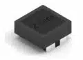
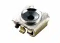
The SD25 duplexers and SF25/SF20 filters provide band-specific signal separation for base stations and customer premises equipment, with 2520 and 2016 package options.
Key features and benefits
- The SD25 duplexer range covers Bands 1, 3, 7, 8, 25, 28 and 66, with separate transmit, receive and antenna ports.
- The SF25 filter range includes transmit, receive and combined transmit/receive functions for selected FDD and TDD bands.
- The SF20-2595M3UUA1 Band 41 filter measures 2.0 ± 0.1 mm × 1.6 ± 0.1 mm, with a maximum height of 0.9 mm.
- The SF25-2140R9UUA1 Band 1 transmit filter has typical insertion loss of 0.8 dB and maximum insertion loss of 1.4 dB, averaged over any 10 MHz within 2110–2170 MHz.
- All devices in the base-station lineup are in mass production.
The temperature-compensated SAW technology underpins both the duplexer and filter portfolio. Selection remains band- and circuit-specific: passband loss, stopband attenuation, transmit-to-receive isolation, matching and input-power conditions determine the appropriate device.
Technical highlights
SD25 duplexers for FDD signal separation
The SD25 family uses the 2520 package format and unbalanced ports. Its band-specific transmit and receive paths share an antenna connection.
| Part number | Band | Tx passband | Rx passband |
|---|---|---|---|
| SD25-2140R9UUA1 | 1 | 2110–2170 MHz | 1920–1980 MHz |
| SD25-1842R9UUA1 | 3 | 1805–1880 MHz | 1710–1785 MHz |
| SD25-2655R9UUA1 | 7 | 2620–2690 MHz | 2500–2570 MHz |
| SD25-0942R9UUA1 | 8 | 925–960 MHz | 880–915 MHz |
| SD25-1962R9UUA1 | 25 | 1930–1995 MHz | 1850–1915 MHz |
| SD25-0780R9UUA1 | 28 | 758–803 MHz | 703–748 MHz |
| SD25-2155R9UUA1 | 66 | 2110–2200 MHz | 1710–1780 MHz |
The Band 8 SD25-0942R9UUA1 measures 2.5 ± 0.1 mm × 2.0 ± 0.1 mm, with a maximum height of 0.9 mm. Its operating temperature range is −40 °C to +95 °C.
For this device, transmit insertion loss is 1.3 dB typical and 2.2 dB maximum; receive insertion loss is 1.4 dB typical and 2.5 dB maximum. These values are averaged over any 5 MHz within their respective passbands. Minimum transmit-to-receive isolation is 55 dB across 880–915 MHz and 49 dB across 925–960 MHz, using the same averaging bandwidth.
Insertion loss and isolation serve different circuit requirements. The former governs attenuation through the wanted signal path; the latter governs separation between transmit and receive ports. Both need to be included in the RF budget rather than reduced to a single headline figure.
SF25 and SF20 standalone filters
The standalone lineup provides separate transmit, receive and combined transmit/receive filtering functions.
| Part number | Band | Function | Passband |
|---|---|---|---|
| SF25-2140R9UUA1 | 1 | Tx | 2110–2170 MHz |
| SF25-1950R9UUA1 | 1 | Rx | 1920–1980 MHz |
| SF25-0847E9SSA1 | 8 + 20 | Rx | 832–862 / 880–915 MHz |
| SF25-0725R9UUA1 | 28 | Rx | 703–748 MHz |
| SF25-2345R9UUA1 | 40 | TRx | 2300–2390 MHz |
| SF20-2595M3UUA1 | 41 | TRx | 2515–2675 MHz |
Band-edge behaviour can materially affect selection. The SF25-1950R9UUA1 has typical insertion loss of 3.0 dB and maximum insertion loss of 8.0 dB across 1920–1925 MHz. Across 1925–1980 MHz, these values are 1.9 dB and 2.9 dB. A channel plan near the lower passband edge therefore needs a different loss budget from one further inside the band.
The SF20-2595M3UUA1 has typical insertion loss of 2.6 dB and maximum insertion loss of 3.5 dB across 2515–2675 MHz. Attenuation across 2400–2483.5 MHz is 42 dB minimum and 46 dB typical. Its operating temperature range is −40 °C to +95 °C.
Temperature capability also varies by part. The SF25-0847E9SSA1 dual-band receive filter and SF25-0725R9UUA1 Band 28 receive filter operate from −40 °C to +105 °C.
Typical applications
Target applications include macro-cell and small-cell communication base stations, together with customer premises equipment.
- FDD transmit/receive separation: the SD25 duplexers combine paired transmit and receive passbands with an antenna port. The Band 8 device supports 925–960 MHz transmission and 880–915 MHz reception.
- Separate transmit filtering: the SF25-2140R9UUA1 provides a 2110–2170 MHz Band 1 transmit path, with maximum insertion loss of 1.4 dB averaged over any 10 MHz.
- Dual-band receive filtering: the SF25-0847E9SSA1 covers the Band 20 and Band 8 receive ranges. Average insertion loss is 1.5 dB typical and 3.0 dB maximum over any 5 MHz in either passband.
- TDD transmit/receive filtering: the SF25-2345R9UUA1 covers 2300–2390 MHz, while the SF20-2595M3UUA1 covers 2515–2675 MHz.
Design-in notes for engineers
- Match the ports, not just the nominal system impedance. The SF20-2595M3UUA1 measurement circuit uses a 3.9 nH shunt inductor at the transmit/receive port and a 5.6 nH shunt inductor at the antenna port, with 50 Ω terminations. These are ideal inductance values; the implemented matching network and PCB layout form part of the RF design.
- Budget maximum loss and minimum rejection. Typical values help characterise a device, but maximum insertion loss and minimum attenuation or isolation determine the design margins. Preserve each value’s frequency range and averaging bandwidth.
- Keep input-power conditions attached to the rating. The SF20-2595M3UUA1 has a maximum input-power rating of 32 dBm for a 5 MHz LTE signal with an 8.0 dB peak-to-average ratio and 40% duty cycle, under the 10-year, +95 °C condition. This is not a continuous-wave rating.
- Use the part-specific land pattern and pin allocation. Package size alone does not define connectivity. The SF25-0847E9SSA1 uses pin 1 for receive and pin 3 as open; the SF25-0725R9UUA1 uses pin 3 for receive and pin 1 as open.
- Plan moisture-sensitive assembly handling. The devices have moisture sensitivity level 3. After opening moisture-proof packaging, mounting should take place within 168 hours at 5–30 °C and no more than 60% relative humidity. The SF20 product guidance recommends up to three reflow cycles.
- Validate the assembled RF path under the actual operating conditions before production release.
Further reading
- Passive Filter Technologies Compared: LC, Ferrite, Feedthrough, Ceramic, Cavity, Microstrip, SAW and BAW
- RF Inductors and Filters: Guide to Selection, Design and LTCC Solutions
Source
This article is based on the Kyocera product announcement and official product documentation. Engineers should refer to the current manufacturer datasheet for final design and qualification.
References
- Miniaturized and Lightweight SAW Devices for Base Stations, Kyocera.
- SD25-2140R9UUA1 SAW Duplexer Datasheet, Kyocera.
- SD25-1842R9UUA1 SAW Duplexer Datasheet, Kyocera.
- SD25-2655R9UUA1 SAW Duplexer Datasheet, Kyocera.
- SD25-0942R9UUA1 SAW Duplexer Datasheet, Kyocera.
- SD25-1962R9UUA1 SAW Duplexer Datasheet, Kyocera.
- SD25-0780R9UUA1 SAW Duplexer Datasheet, Kyocera.
- SD25-2155R9UUA1 SAW Duplexer Datasheet, Kyocera.
- SF25-2140R9UUA1 Band 1 Tx Filter Datasheet, Kyocera.
- SF25-1950R9UUA1 Band 1 Rx Filter Datasheet, Kyocera.
- SF25-0847E9SSA1 Band 8 + 20 Rx Filter Specification, Kyocera, February 24, 2023.
- SF25-0725R9UUA1 Band 28 Rx Filter Datasheet, Kyocera.
- SF25-2345R9UUA1 Band 40 TRx Filter Datasheet, Kyocera.
- SF20-2595M3UUA1 Band 41 TRx Filter Datasheet, Kyocera.
- SF20-2595M3UUA1 Product Information, Kyocera.
- SD25-0942R9UUA1 Product Information, Kyocera.