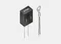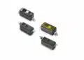
YAGEO Group has introduced the AS Series of resin-coat-less multilayer piezoelectric actuators for high-speed industrial motion and vibration-control systems.
The initial AS0505D20H20NF device combines a 120 V DC maximum drive rating, 19 ±3 µm displacement and 650 N generated force in a 5.2 mm × 5.2 mm × 20 mm actuator element.
Key features and benefits
- High-speed operation is specified up to 1 kHz.
- The AS Series uses a resin-coat-less multilayer construction with stacked partial electrodes.
- The published operating-temperature range is −25 °C to +150 °C.
- The initial released part is AS0505D20H20NF.
- The actuator offers 19 ±3 µm displacement at 120 V DC, with a generated force of 650 N when displacement is constrained to zero.
- Capacitance is 1.2 µF with ±20% tolerance, measured at 1 kHz and 1 V rms.
- RoHS and REACH compliance is specified.
- The part is supplied with 100 mm, AWG 30 copper lead wires with tin plating and PTFE insulation.
The new AS family extends YAGEO Group’s multilayer piezoelectric actuator range with a high-speed, resin-coat-less option. Its published characteristic curves include displacement-versus-voltage, force-versus-displacement, temperature-versus-displacement, and drive-frequency-versus-maximum-voltage data for the initial part.
Technical highlights
| Parameter | AS0505D20H20NF | Selection relevance |
|---|---|---|
| Maximum drive voltage | 120 V DC | Driver and insulation design |
| Displacement at 120 V DC | 19 ±3 µm | Motion range |
| Generated force | 650 N | Blocked-force condition |
| Capacitance | 1.2 µF ±20% | Driver current demand |
| Insulation resistance | 50 MΩ | Leakage performance |
| Dissipation factor | 5% maximum | Self-heating consideration |
| Stiffness | 34 N/µm | Mechanical-load matching |
| Operating temperature | −25 °C to +150 °C | Ambient and thermal margin |
| Ceramic cross-section | 5.2 mm × 5.2 mm | Mounting envelope |
| Overall length | 20 mm ±0.1 mm | Mechanical integration |
| Weight | 5.0 g | Moving-mass budget |
The AS0505D20H20NF has a maximum outer envelope of 6.0 mm by 8.0 mm around the termination region. Its lead wires are AWG 30, with a 0.3 mm conductor diameter, 0.5 mm outer diameter and 100 mm length.
The 650 N figure is not a continuous external-load rating. It is the force required to restrict displacement to zero at the maximum 120 V DC drive voltage. Mechanical-system design therefore needs the published force-displacement curve and the stiffness value rather than relying on free displacement or blocked force alone.
The product brief is revised 2026-04-24. It gives a 1 kHz high-speed capability, but its frequency-versus-maximum-drive-voltage curve shows that permissible drive voltage must be checked against the selected operating frequency. For the AS0505D20H20NF, the accompanying thermal plot uses a 50% duty square-wave condition and shows separate traces for 500 Hz at 120 V 0-peak, 1 kHz at 100 V 0-peak, and 2 kHz at 80 V 0-peak.
Typical applications
The published application examples cover precision movement, vibration generation, vibration damping and positioning functions rather than power-electronic circuit positions.
| Application | Published support | Engineering focus |
|---|---|---|
| Vibration source and control | Up to 1 kHz operation; 650 N force | Frequency and thermal rise |
| Optical positioning | 19 ±3 µm displacement; 34 N/µm stiffness | Alignment and hysteresis |
| Dispensers and manipulators | 120 V DC drive; compact 20 mm length | Load-axis alignment |
| Semiconductor equipment | Fast response; 5.2 mm × 5.2 mm cross-section | Fixture rigidity |
| Pumps and valves | Published actuator application examples | Stroke under real load |
| Measuring instruments | Fine-positioning and sensor examples | Repeatability validation |
| Medical equipment | Micropump, ultrasonic-transducer and manipulator examples | System-level qualification |
Published examples include vibration sources and vibration-control systems, mirror and prism positioning, manipulators, motors, printers and dispensers. The product documentation also lists wire-bonding clamps, shakers, damping systems, robot systems, pumps, speaker systems, autofocus mechanisms, positioning stages, polarization and wavelength control, micropumps, ultrasonic transducers, pressure sensors and acceleration sensors.
The temperature range to +150 °C and the compact 5.2 mm × 5.2 mm ceramic cross-section are relevant where the actuator must fit close to a heat-generating mechanical assembly. That temperature limit must include self-heating from the selected waveform, duty cycle and frequency; it is not simply an ambient-temperature allowance.
Design-in notes for engineers
- Size the driver for capacitive charge and discharge current, not only the 120 V DC maximum voltage. The 1.2 µF capacitance, drive waveform, edge rate and supply impedance determine current stress and self-heating.
- Keep the applied voltage within the frequency-dependent limits shown in the current product documentation. The 120 V DC maximum rating does not automatically apply at every pulse frequency and waveform.
- Align the mechanical load axis with the actuator displacement axis. Side contact, bending, twisting, tensile load and misalignment can damage the ceramic element.
- Install the actuator so that its displacement axis is vertical to the mounting surface, as specified in the user guide.
- Use a rigid adhesive joint if bonding is required. The documentation recommends epoxy-based adhesives with sufficient rigidity and a controlled medium thickness; adhesive should not be formed on the sides of the actuator.
- The user guide gives reference limits of 0.3 N·m or less for twisting force and 50 N or less for tensile force, although these are stated as general reference values rather than AS0505D20H20NF-specific operating ratings.
- Do not apply reverse voltage. The red lead wire connects to the positive terminal and the white lead wire to the negative terminal.
- Account for hysteresis, creep and ringing in the position-control loop. The documentation requires transient response time to remain below one-third of resonant frequency to reduce ringing-related damage.
- Validate actuator temperature under the final voltage waveform, frequency, duty cycle, fixture and ambient conditions. The drive frequency, pulse waveform and mechanical mounting all affect self-heating.
- For dynamic pulse testing of AS0505D20H20NF, the datasheet reports no confirmed failures after 1 billion cycles at 1 kHz with a 0–120 V rectangular pulse. This is a stated test result, not a replacement for lifetime validation in the finished mechanism.
- Store the resin-coat-less AS Series at −5 °C to +40 °C, below 40% RH and without condensation. The documentation also calls for polarization after exposure above 100 °C or storage longer than three months.
- The actuator is RoHS and REACH compliant, but the documentation identifies PZT as the main piezoceramic ingredient and notes a REACH SVHC declaration. Material and disposal requirements should be reviewed for the intended market and finished equipment.
Further reading
- MLCC and Ceramic Capacitors
- Researchers Demonstrated 32nm Aluminum Vacuum Gap Capacitor
- KEMET Video Explains Haptic Actuator Function and Applications
- CTO interview: KEMET celebrates 100 years
Source
This article is based on the YAGEO Group AS Series product announcement and official AS Series product documentation. Engineers should consult the current manufacturer datasheet, characteristic curves and handling documentation before final qualification, mechanical design and production release.