source: LEDs magazine article
Published on:August 7, 2017 By Phil Ebbert Riedon Inc.
Small components such as ballast resistors can have a big impact on SSL designs when they are specified appropriately and LEDs are biased for optimal operation, says PHIL EBBERT.
Specifying a resistor might seem easy, but for many uses it is necessary to comprehend every aspect of the application’s requirements. This is especially true in newer markets, such as high-power LED lighting.
Interested in articles & announcements on LED & SSL design?
This article will investigate how LEDs operate and how to correctly bias the LED for the optimal lighting performance. The article will also look at the operating characteristics of the LED to find out the best topology for lighting installations, and how driving LEDs in series can be more efficient. It will show the importance of temperature stability in maximizing the output, as well as keeping the color regular, enhancing reliability, and prolonging operating life.
An understanding of the principles behind biasing of LED-based solid-state lighting (SSL) will show that the ballast resistor will be responsible for dissipating several watts. To carry out this task requires a high-power resistor that may need heat sinking. This requirement complicates the design, but is necessary for the optimal operation of the LED.
It is important to demonstrate practical solutions alongside theoretical examples. For these practical examples, the article will use resistors from resistor manufacturer and supplier Riedon. The main ranges that will be highlighted are the UT series wirewound resistors that can dissipate up to 13W, and the PF power film range that can dissipate 20W. Alternative choices will also be presented for applications that require heat sinking, or for surface mounting.
LED operation and biasing
An LED is a semiconductor that works similarly to any other type of diode, except that when the current is applied across the p-n junction, light is given off (see this short article from LEDs Magazine’s archive). To get the LED to produce light, a DC supply must provide a forward-biased voltage across the LED’s junction.
LEDs that are specifically designed for lighting applications generally operate from a voltage of around 3V. Fig. 1 shows that the voltage/current relationship is nonlinear. As the voltage increases, the LED draws a much higher current. However, this higher current does not equate to an equal amount of additional light, as the current’s relationship to the luminous flux (light measurement) is also nonlinear.

FIG. 1. Typical LED current versus voltage characteristic.
To get more light efficiently requires adding more LEDs, rather than more current. Taking these requirements into account, current through the LED should be limited to keep the LED operation optimal. The traditional way of doing this, and the easiest, is through Ohm’s Law and using a resistor in series, as shown in Fig. 2.
IF = (VDC – VF)/R
Where IF = forward current, VDC = supply voltage, VF = forward voltage, and R = ballast resistor.

FIG. 2. Simple LED biasing circuit.
LEDs can be operated directly from a mains voltage that has been converted by a rectifier and smoothed, but the voltage value of the supply will be many times more than is required for the bias voltage of the LED. There will be a large amount of power wasted by the ballast resistor in comparison to that used productively in the LED. LEDs can be connected in series, which will give a number of separate voltage drops. This makes the circuit more efficient, but at the end of the day, there will still be a large amount of the overall circuit power wasted by the ballast resistor.
One way to maximize the efficiency of the circuit is to use a power supply with an output designed specifically to power LEDs. These power supplies take the mains AC input, and output a DC signal that can drive either a single LED or, more often, a string of LEDs that can operate up to 60V. Even if we look at the “60W” LED fittings that are sold as a direct replacement for incandescent bulbs, the principle is the same. These fittings have an integrated driver circuit that takes the AC mains and performs a conversion to DC to power the LEDs. This technique also facilitates the ability to connect parallel LEDs or strings. Each of these parallel circuits will require its own ballast resistor placed in series to regulate the current.
Selecting the correct ballast resistor
The ballast resistor can be chosen after running the bias circuit numbers and LED characteristics through a couple of simple calculations. If the circuit has a string of six LEDs in series, each of which has a forward voltage requirement of 3V, and our supply is 24 VDC, there will be a 6V drop from the ballast resistor. If the forward current is 350 mA, then the resistor value can be calculated as:
R = (VDC – 6 × VF) / IF = (24 – 6 × 3) / 0.35 = 17.1Ω
And the power dissipated by the resistor:
P = V × I = 6 × 0.35 = 2.1W
So far, so good. Now we have the basic specifications required to meet the circuit’s needs. But before actually picking the physical device, it is helpful to have a deeper look to see if our assumptions hold true every time. Why would the circuit need a 24V output, when a 20V should suffice and waste much less power? It might simply be down to tolerances. In actual operation, power supplies may have an output that has ±5% tolerance. Although the characteristics of the LEDs can have an effect on the circuit, most of the variance would be in the voltage dropped across the resistor. In the example above, the tolerance may lead to a 1.2V increase in the supply voltage, and a 50-mA increase in the current to 400 mA, which is not too difficult for the circuit to handle. If we had used the 20V power supply, the voltage could possibly rise as high as 1V, leading to a current of 450 mA in the circuit, which is a much higher percentage of the nominal current.
Other events that can affect the current drawn are variations in the value of the resistor or the LEDs. The fact that each element of the simple circuit can change in value must be taken into account when designing the overall circuit. If a disproportionate amount of current is drawn, it could lead to temperature increases in the junction of the LED. As mentioned earlier in the article, the excess current is not converted efficiently into light, and the higher temperature can reduce the reliability of the LED, as well as its operational lifetime.
It is not just the LED’s lifetime that can be affected; the variation in current and temperature also affects the chromaticity, or color tone, of the light output, which could be more important for a lighting circuit.
Many LED lighting circuits require dimming, which can be accomplished by varying the drive current, but this also has the same drawbacks with variations in the output chromaticity. More frequently, pulsewidth modulation (PWM) is used on the bias current for dimming purposes. The LEDs are driven using a rectangular waveform, which is switched on and off at frequencies (100 kHz or larger) that are too high to be seen by the human eye. This type of dimming also saves power. The LEDs are fed the nominal current when the cycle is high, while there is very little power dissipated when the cycle is low. If the circuit is to use PWM for dimming, the ballast resistor must be nonreactive.
Resistors for LED ballast applications
The forward current rating of the LED is the most important characteristic when designing the circuit. Traditionally, 350-mA LEDs were the most commonly used, though recently 700-mA, 1A, and 1.5A forward current LEDs are becoming much more popular. In the example earlier in this article, it was demonstrated that a resistor that could dissipate just over 2W would be sufficient. LEDs with higher forward current ratings will require a resistor that could be rated as high as 10W.
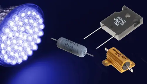
One type of resistor that could be used for ballast is the common axial wirewound resistor. This type of resistor has decent power capability, low tolerance, a low TCR (temperature coefficient of resistance), and is able to operate normally over a broad temperature range. Riedon’s UT range of wirewound resistors is a good example of this type of device. Devices in the range can handle up to 13W power and operate over a very wide temperature range (-55oC to +250oC) with low TCR. If the circuit is using LEDs where higher dissipation is required, or where it is important that the temperature is kept stable, Riedon’s UAL range of aluminum-housed wirewound power resistors are rated to over 50W.

FIG. 3. Riedon resistors for LED lighting.
Wirewound resistors may have larger inductances than would be acceptable in some PWM circuits, but noninductive winding techniques are usually used these days. Another potential choice for PWM applications is thin-film resistors. For example, Riedon’s PF series features low-inductance resistors that have different package types to support a variety of power needs. The TO-126 package can handle up to 20W, and the TO-220 package up to 50W. If a surface-mount resistor is required, the PFS series can handle 35W.
PHIL EBBERT is vice president of engineering at Riedon Inc.