











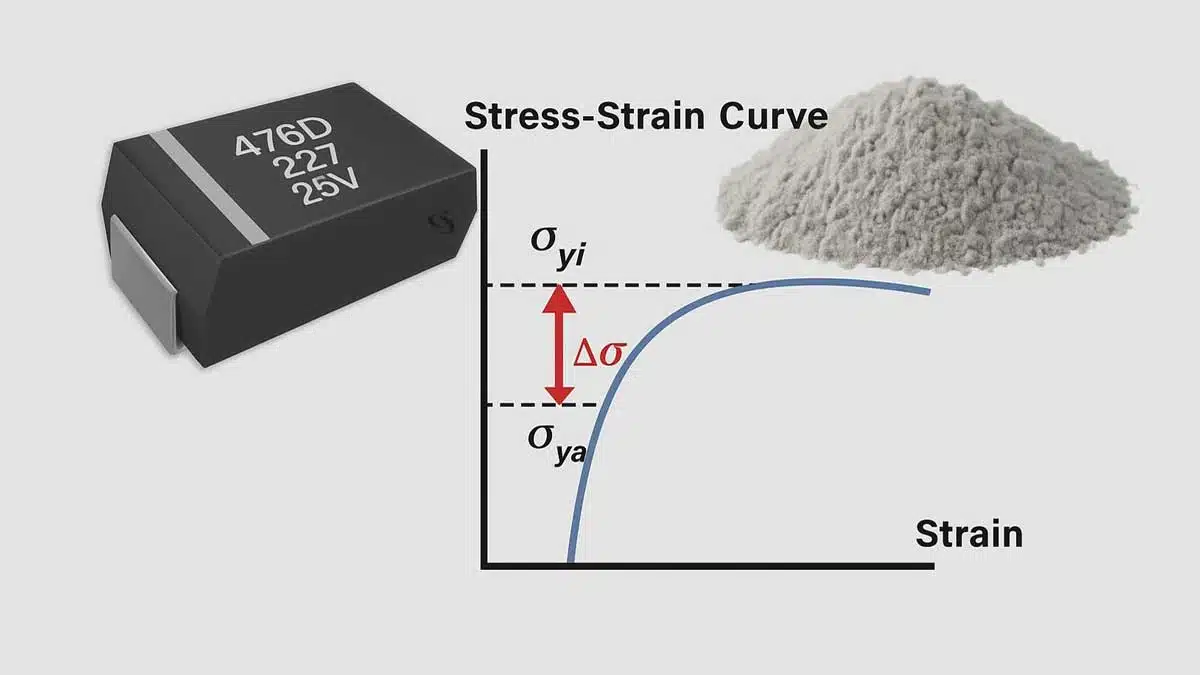
Dr. Vladimir Azbel, an independent consultant on tantalum capacitors, presents a tantalum powder mechanical testing methodology in this paper. This methodology utilizes stress–strain curve (SSC) parameters and the Δσ benchmark as an alternative to the conventional Wet Test for inspecting tantalum powder. The goal is to enhance the yield and reliability of tantalum capacitors.
Introduction
The Wet Test measures electrical characteristics (capacitance and leakage current) but fails to capture structural factors responsible for long-term reliability.
By analyzing the relative change in yield strength before and after annealing (Δσ), internal stresses within porous anodes can be quantified. Δσ directly reflects structural stability and serves as an objective, reproducible indicator of aging tendency.
The method enables early differentiation of stable from problematic powder lots and provides predictive insight into long-term performance.
The Wet Test is traditionally applied for the incoming inspection of tantalum powders. The evaluation criterion involves comparing capacitance (C) and direct current leakage (DCL) of anodes fabricated according to a standard recipe with results obtained from previously qualified powder lots of the same grade.
- Capacitance and morphology: Capacitance is determined by pore surface area, which can be achieved with different morphologies. However, it is directly related to the primary particle size distribution, which is difficult to verify because the powder is typically supplied in an agglomerated form.
- DCL and internal stresses: DCL stability depends on internal stresses formed during the growth of the amorphous Ta2O5 film. These stresses arise from both the exothermic oxidation reaction and the mismatch in thermal expansion coefficients between Ta and Ta2O5.
- Neck size distribution: Neck size distribution between particles plays a decisive role. It determines whether stresses can relax during oxide growth or accumulate, leading to defects and degradation.
Problem statement
Currently, tantalum capacitor manufacturers do not mandatory request the primary particle size distribution curve, even though it is the key determinant of porosity. As a result, capacitance can be reproduced with different morphologies. However, non-uniform porosity leads to variation in neck sizes, which in turn increases DCL variability and decreases overall reliability.
Mechanical alternative: stress–strain curve and Δσ benchmark
To overcome these limitations, a mechanical testing method has been introduced based on the analysis of stress–strain curve (SSC) parameters and the Δσ benchmark. This approach was adapted from studies on the aging of heat-resistant materials.
Definition of Δσ
Δσ denotes the relative change in yield strength before and after annealing, as obtained from the stress–strain curve. It originates from the relaxation of internal stresses locked within the porous structure during thermal treatment.
If an anode contains substantial internal stresses—arising from variations in the granulometric composition of primary particles, pressing conditions, insufficient mixing, or temperature gradients during sintering—structural rearrangements occur during annealing. These changes manifest as a shift in yield strength. Consequently, Δσ directly reflects structural stability.
Principle of the method
- Low Δσ: Minimal internal stresses, stable structure, negligible risk of aging, and very low failure probability.
- High Δσ: Significant internal stresses, pronounced aging processes, structural degradation, and elevated DCL.
Thus, Δσ serves as a reliable indicator of the material’s tendency toward aging.
Structural information from the SSC curve
- Yield strength: Indicates the average neck size between particles, enabling monitoring of morphology within a given powder grade.
- Elastic modulus: Reflects the overall porosity of the material.
- Strain-hardening coefficient: Characterizes defect density and the level of residual stresses.
Comparison of the SSC curve of a new powder lot with a benchmark allows early assessment of structural quality and suitability. Nevertheless, Δσ remains the most reliable quantitative criterion.
Practical implementation
For incoming inspection, benchmarks are established for both the stress–strain curve and Δσ. These benchmarks are determined once using a qualified powder lot and subsequently serve as reference values for all future lots of the same grade. The same methodology can be applied to monitor ongoing production batches of anodes.
Experimental Validation
Experiment 1. Δσ as a predictor of DCL stability when electrical tests show no difference
To test the predictive capability of the proposed method, tantalum capacitor samples of identical design, manufactured with the same technological process from five different powder lots, were investigated. The powder grade was 50kCV from two leading suppliers.
All five lots successfully passed conventional electrical evaluation (Wet Test, Silver Check, Final Test, Life Test). Electrical test data are summarized in Table 1, where no substantial differences can be observed at the early inspection stages. Notably, press pellets from all batches were sintered in the same furnace run.
Experiment results
- Early tests: Wet Check, Silver Check, and Final Test values were essentially the same across all lots (see Table 1).
- End-of-life behavior: Significant differences appeared in end-of-life DCL (2000 h test), reflected in the number of rejects.
| Lot | Wet DCL (µA) | Silver DCL (µA) | EOL DCL (µA) | Electrical yield (%) / Rejects |
|---|---|---|---|---|
| 1 | 1.87 | 2.12 | 4.94 | 95.83 / 0+2+0 |
| 2 | 2.72 | 9.61 | 6.29 | 77.33 / 4+2+2 |
| 3 | 1.51 | 4.63 | 5.81 | 95.73 / 4+1+1 |
| 4 | 2.25 | 4.55 | 4.12 | 75.17 / 0 |
| 5 | 2.15 | 3.15 | 4.82 | 76.18 / 1+0+0 |
Δσ calculation
For the corresponding anodes, yield strength was determined before annealing (σy,i) and after annealing at 450 °C in air (σy,a). The relative change Δσ was calculated as:
Equation: Δσ% = (σy,i − σy,a) / σy,i × 100
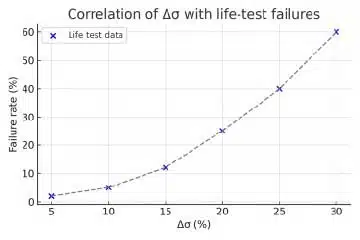
The correlation between Δσ and the reject rate demonstrated that lots with higher Δσ values exhibited higher failure probability, despite indistinguishable results in the standard electrical tests. This confirms that Δσ can serve as an early and reliable indicator of structural instability and long-term degradation risk.
Experiment 2. Identification of problematic batches via mechanical parameters
During subsequent production, new batches from the same powder grade exhibited unexpectedly high leakage currents already at the incoming inspection stage. Certificates indicated all parameters within specifications, and for more than 40 previous batches of the same powder, no such issues had been observed.
Comparative data for acceptable (40 lots) and problematic (5 lots) batches are summarized in Table 2, showing differences in carbon content, shrinkage, and DCL behavior.
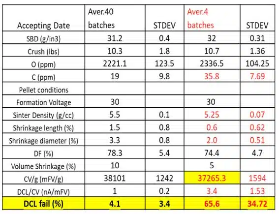
Since the powders were nominally identical and pressed under the same recipe, a detailed mechanical analysis was conducted using stress–strain curves. The key mechanical parameters—yield strength, elastic modulus, and strain-hardening coefficient—were extracted.
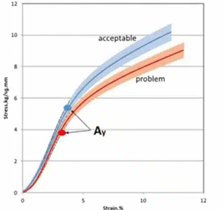
The stress–strain curves revealed that in the problematic lots, the yield strength was approximately 30% lower compared to the acceptable ones (see Figure 2). Yield strength is proportional to average neck size between particles. A reduction in neck size under the same formation voltage increases internal stresses already at the forming stage, thereby predisposing the material to high leakage currents and reduced reliability.
Final remarks
The two presented case studies clearly demonstrate that mechanical testing provides critical information inaccessible through traditional Wet Test evaluation. In Experiment 1, Δσ successfully predicted long-term DCL degradation in cases where all electrical tests initially showed no differences. In Experiment 2, mechanical analysis of stress–strain parameters revealed the root cause of high leakage currents in newly supplied batches, even though the supplier data met specifications.
Thus, Δσ and related SSC parameters not only complement electrical testing but also serve as indispensable tools for early detection of problematic powder lots and prediction of their long-term reliability.
Conclusion
In summary, Δσ provides an objective and reproducible reliability criterion, enabling early differentiation between stable and problematic powder lots. Unlike the Wet Test, which captures only instantaneous electrical parameters, the Δσ-based approach reveals the underlying structural state and allows prediction of its long-term evolution. This makes it a powerful tool for ensuring the reliability of capacitor-grade tantalum powders.
To further substantiate the method, two experimental case studies were conducted. They demonstrate how mechanical parameters (in particular yield strength and Δσ) can provide critical insights even in situations where electrical testing shows no deviations, or where unexpected DCL problems arise in new batches.
References
Vladimir Azbel: Structural Interpretation of Reliability in Tantalum Capacitor Anodes












