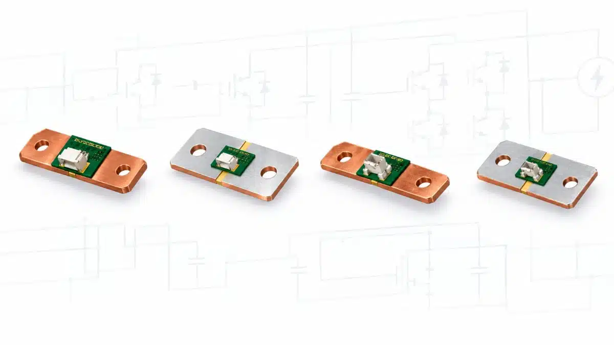
Bourns has introduced the CSI2F-6918, CSI2F-7036, CSI2F-8518 and CSI2F-8536 current sense resistor series for low-resistance measurement in high-current power paths.
The four large-format shunt families combine resistance values from 25 µΩ to 200 µΩ with a 36 W continuous-power rating at a 125 °C terminal temperature, addressing designs where insertion loss, thermal loading and measurement accuracy must be managed together.
Key features and benefits
- Four new current sense resistor series: CSI2F-6918, CSI2F-7036, CSI2F-8518 and CSI2F-8536
- Resistance range from 25 µΩ to 200 µΩ across the complete release
- 36 W continuous-power rating at a 125 °C terminal temperature
- Operating-temperature range from −40 °C to +125 °C
- ±5% resistance tolerance
- TCR of less than 50 ppm/°C for the resistance alloy
- TCR on test points of ±150 ppm/°C
- Horizontal or vertical connection configurations
- Bare-copper or tinned terminals, with the higher resistance options limited to bare-copper terminal versions
- Maximum fastening torque of 10 Nm
- RoHS compliant and lead free
The new families add bolt-down, ultra-low-ohmic options to the Bourns current-sense resistor range in 6918, 7036, 8518 and 8536 case formats. These are physically large resistor formats intended for direct integration into high-current conductors rather than conventional small-signal PCB current measurement.
Technical highlights
| Series | Case size | Resistance range | Continuous power |
|---|---|---|---|
| CSI2F-6918 | 6918 | 50–200 µΩ | 36 W |
| CSI2F-7036 | 7036 | 25–100 µΩ | 36 W |
| CSI2F-8518 | 8518 | 50–200 µΩ | 36 W |
| CSI2F-8536 | 8536 | 25–100 µΩ | 36 W |
| Parameter | Specification | Selection relevance |
|---|---|---|
| Continuous power | 36 W at 125 °C terminal | Thermal margin |
| Operating temperature | −40 °C to +125 °C | Ambient limit |
| Resistance tolerance | ±5% | Initial error |
| Alloy TCR | <50 ppm/°C | Temperature drift |
| Test-point TCR | ±150 ppm/°C | Measurement-path drift |
| Fastening torque | 10 Nm maximum | Mechanical assembly |
The resistance value determines both sense voltage and dissipation. A lower-value shunt reduces voltage drop and conduction loss in the main power path, but it also reduces the signal available to the current-sense amplifier or ADC. At micro-ohm resistance levels, the electrical contribution of bolts, busbars, terminals, PCB copper and sense-tap placement can become significant relative to the shunt resistance itself.
The distinction between the alloy TCR and the TCR measured on the test points also matters. The alloy figure describes the temperature coefficient of the resistive element, while the test-point figure incorporates the practical measurement path through the resistor assembly. Accuracy calculations should therefore use the test-point specification where the circuit senses voltage at those terminals.
Typical applications
The release identifies battery management systems, busbar current sensing, welding equipment, frequency converters and industrial equipment.
- Battery-management systems: The 25 µΩ to 200 µΩ range and 36 W rating support current monitoring in high-current charge and discharge paths where a small burden voltage is required.
- Busbar current sensing: The bolt-down formats, horizontal or vertical connections and 10 Nm fastening-torque limit support mechanical integration into busbar-connected current paths.
- Welding equipment: The 36 W rating at a 125 °C terminal temperature supports applications with substantial continuous thermal loading, subject to validation of the actual current waveform and pulse profile.
- Frequency converters: The low resistance range limits steady-state voltage drop in inverter or converter current paths, while the −40 °C to +125 °C operating range defines the specified environmental limit.
- Industrial power equipment: The combination of ultra-low resistance, 36 W continuous dissipation and selectable case geometry supports current-monitoring functions where the current path is implemented with robust copper conductors or busbars.
Application fit
| Circuit position | Supporting specifications | Primary design check |
|---|---|---|
| Battery current shunt | 25–200 µΩ, 36 W | Error budget |
| Busbar monitor | Bolt-down formats, 10 Nm | Contact resistance |
| Welding equipment | 36 W at 125 °C | Pulse loading |
| Frequency converter | <50 ppm/°C alloy TCR | Thermal drift |
| Industrial power path | −40 °C to +125 °C | Enclosure temperature |
For a current-sensing circuit, the resistor is installed in series with the load and produces a voltage proportional to current. The low-value range is useful when system efficiency and allowable voltage drop are constrained, but the measurement chain must be sized for the resulting low sense voltage. Amplifier input offset, gain accuracy, common-mode range, noise, ADC resolution and connection resistance all need to be included in the overall measurement budget.
The release uses the CSI2F designation, while Bourns’ current product selector presently lists closely related CSM2F families in the same 6918, 7036, 8518 and 8536 case formats. The publicly indexed CSM2F entries list 36 W for the 6918 and 8518 formats, but 50 W for the 7036 and 8536 formats. This article follows the new CSI2F release for the 36 W rating; engineers should verify the exact CSI2F part-number datasheet before selecting a replacement for an existing CSM2F design.
Design-in notes for engineers
- Select the resistance from the full measurement budget. Include the required full-scale sense voltage, allowable insertion loss, amplifier offset and ADC resolution rather than selecting only from continuous-power capability.
- Use Kelvin sensing where accuracy matters. Route voltage-sense connections directly from the intended sensing points, separately from the high-current conductor path. Busbar, bolt, terminal and cable resistance can otherwise enter the measurement result.
- Assess the installed thermal environment. The 36 W rating is specified at a 125 °C terminal temperature. Validate the selected case size with the final busbar geometry, conductor cross-section, enclosure temperature, airflow and nearby heat sources.
- Check the entire current profile. Continuous dissipation, overload, inrush, short-circuit, regenerative and repetitive-pulse conditions are separate requirements. The release identifies a high pulse-power capability but does not provide public pulse-energy curves or test conditions.
- Apply the fastening limit. Do not exceed the specified 10 Nm maximum torque. Tightening method, washer stack, conductor surface condition and joint relaxation over temperature should be evaluated in the final mechanical assembly.
- Choose terminal finish deliberately. Bare-copper and tinned-terminal configurations are available, but the release limits specified higher-resistance options to bare-copper versions. Confirm the selected ordering code, plating requirement and assembly process before procurement release.
- Treat TCR as a system-level accuracy variable. Use the ±150 ppm/°C test-point TCR when calculating the measured resistance change through the practical sensing path, then combine it with self-heating and thermal gradients in the busbar assembly.
- Confirm current documentation before release. No CSI2F-specific datasheet, outline drawing, land-pattern guide, qualification report, reliability report, SPICE model, impedance curve, derating curve or product-change notice was publicly located in the official material reviewed for this announcement. This should be verified under final operating conditions before schematic, mechanical and production release.
Further reading
- Bourns Extends Current Sense Resistors for High-Current Power Designs with 0.1 mΩ, 15 W
- Understanding Basics of Current Sense Resistors
- Bourns CRH2512 5 W Current-Sense Resistors
Source
This information is based on the Bourns new-product release for the CSI2F-6918, CSI2F-7036, CSI2F-8518 and CSI2F-8536 Series and the official Bourns current sense resistor product selector. Engineers should consult the current manufacturer datasheet and all applicable mechanical, thermal, qualification and assembly documentation before final qualification and design release.