


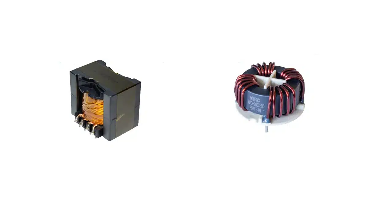
Bourns has released two custom magnetic components, the MAG‑3002584 inductor and the MAG‑3002585 four‑phase line choke, originally developed for Texas Instruments’ high‑power three‑phase flying capacitor inverter reference design TIDA‑010957.
These inductor devices target next‑generation high‑voltage, high‑frequency flying capacitor power conversion systems where power density, efficiency and EMC performance are critical. They are now available as engineering samples through selected distribution partners, giving design teams an off‑the‑shelf starting point for similar architectures.
Key features and benefits
MAG‑3002584 inductor
- High‑power inductor with nominal inductance of 87 µH (±10%) at 0 A, suitable for high‑frequency PFC and inverter stages in three‑phase systems.
- Flat‑wire winding construction that reduces copper losses and improves thermal behavior compared with round‑wire designs in similar footprints.
- Low DC resistance of 10.1 mΩ maximum, enabling high efficiency in applications targeting conversion efficiencies above 98.5%.
- High saturation current of 42 A (specified at 30% inductance drop), providing headroom for transient and ripple currents in demanding high‑power stages.
- Self‑resonant frequency of 1.5 MHz typical, supporting switching in the tens to low hundreds of kilohertz while keeping parasitics under control.
- Thermal current ratings of 15 A (20 °C temperature rise) and 49 A (54 °C temperature rise) that help engineers size the inductor for the desired thermal budget.
- Low‑profile mechanical design with a height of 51 mm, balancing creepage/clearance and power handling for high‑voltage assemblies.
- Designed for use in the TI TIDA‑010957 three‑phase flying capacitor inverter, which gives engineers a validated reference design context.
MAG‑3002585 four‑phase line choke
- Nanocrystalline four‑phase line choke optimized for three‑phase‑plus‑neutral inverter architectures, supporting systems where a neutral connection is required.
- Four identical windings (L1–L4) with typical inductance of 2.18 mH at 0 A per winding, providing common and differential‑mode impedance for input filtering.
- Wide tolerance window of +50 / −35%, typical for custom magnetics used in EMI line filtering, where impedance over frequency is more critical than nominal L.
- Low typical DC resistance of 1.5 mΩ per winding, minimizing conduction losses in high‑current three‑phase lines.
- High‑pot rating of 2500 Vac, 1 s line‑to‑line at 1 mA max leakage, supporting reinforced isolation requirements in many industrial and EV‑related applications.
- Nanocrystalline core material enabling high permeability and low core losses at the high switching frequencies used in modern inverters.
- Approximate weight around 160 g according to the manufacturer data, useful for mechanical and thermal design considerations.
Common benefits
- Both components are RoHS‑compliant and aimed at high‑voltage, high‑frequency power conversion in compact, high‑power‑density systems.
- Availability as engineering samples via distribution shortens time‑to‑prototype compared with a fully custom magnetics design cycle.
- The option for further customization through Bourns allows fine‑tuning for specific bus voltages, current ratings or mechanical constraints.
Typical applications
These power inductor magnetics are intended for demanding energy infrastructure, data center and e‑mobility power conversion platforms where three‑phase architectures dominate. Typical application areas include:
- Data centers and servers
Used in high‑efficiency front‑end rectifiers, three‑phase PFC stages and isolated DC‑DC converter inputs in rack‑level power shelves. - String inverters for renewable energy
Integration in solar string inverters and similar grid‑tied power stages where high‑voltage DC buses and three‑phase AC outputs require robust PFC inductors and line chokes. - On‑board chargers and fast charging stations
Applied in three‑phase on‑board chargers and off‑board DC fast chargers, particularly in flying capacitor or multi‑level inverter topologies that push switching frequencies higher to reduce passive component size. - General high‑power three‑phase inverters
Suitable for industrial drives, UPS, and other high‑power three‑phase inverter systems that benefit from compact, low‑loss magnetics with validated performance in a TI reference design environment.
In most of these applications, the MAG‑3002584 will appear in the high‑frequency PFC or inverter leg as a main energy‑storage inductor, while the MAG‑3002585 will be used as a multi‑winding line or grid‑side choke providing input EMI filtering and differential‑mode noise suppression.
Technical highlights
MAG‑3002584 high‑power inductor
| Parameter | Typical value / description |
|---|---|
| Inductance at 0 A | 87 µH ±10% |
| DC resistance | 10.1 mΩ max |
| Self‑resonant frequency | 1.5 MHz typ. |
| Saturation current (30% drop) | 42 A |
| Thermal current, 20 °C rise | 15 A |
| Thermal current, 54 °C rise | 49 A |
| Construction | Flat‑wire winding, low‑profile design |
| Target efficiency | > 98.5% system‑level power conversion |
The flat‑wire winding combined with low DC resistance helps reduce both copper loss and hot‑spot temperatures in continuous‑conduction‑mode PFC and inverter stages operating with significant ripple current. The specified saturation current at 30% inductance drop provides a clear design limit when calculating peak flux density based on ripple current and applied volt‑seconds.
The manufacturer references a Q‑factor‑based method for estimating core flux density Bp−p using a proportionality constant, inductance in microhenries and peak‑to‑peak ripple current; designers can then use the core loss versus flux density plot from the datasheet to estimate magnetics loss under specific operating conditions. Practical use means verifying that the chosen operating point remains within acceptable loss and temperature rise limits over the full input and load range.
MAG‑3002585 four‑phase nanocrystalline line choke
| Parameter | Typical value / description |
|---|---|
| Inductance per winding (L1–L4) | 2.18 mH at 0 A |
| Inductance tolerance | +50 / −35% |
| DC resistance per winding | 1.5 mΩ typ. |
| Core material | Nanocrystalline |
| Insulation test (line‑line) | 2500 Vac, 1 s, 1 mA max |
| Weight | 160 g (approximate) |
| Configuration | Four‑winding, three‑phase plus neutral |
The nanocrystalline core provides high permeability and low losses over a broad frequency range, which is especially useful where the inverter switching frequency and its harmonics extend into the hundreds of kilohertz. In practice, this improves differential‑mode noise attenuation and reduces the need for oversized common‑mode chokes or additional filtering elements.
Because this is a line choke used mainly for EMI and grid interface purposes, the relatively wide inductance tolerance is generally acceptable; what matters more is impedance over the relevant frequency range and compliance with conducted emission limits. Designers should rely on the full frequency response curves in the datasheet when doing detailed EMI filter design rather than only the nominal inductance at 0 A.
Design‑in notes for engineers
Selecting MAG‑3002584 for PFC and inverter stages
- Confirm that the 87 µH nominal inductance and 42 A saturation current align with your target power level, switching frequency and permissible current ripple in the PFC or inverter leg.
- Use the manufacturer’s core flux density and core loss guidance (including the Q‑factor‑based flux estimation and core loss vs. flux density plots) to verify that core temperature remains within your safety margins under worst‑case conditions.
- Check that the self‑resonant frequency comfortably exceeds your switching frequency and its main harmonics to avoid excessive parasitic effects.
- Evaluate thermal current ratings against your cooling concept (forced air vs. natural convection) and PCB or busbar layout to ensure that the 20 °C or 54 °C rise specification is realistic in your mechanical environment.
- Incorporate the low‑profile mechanical form factor and 51 mm height into creepage and clearance planning for high‑voltage spacing requirements.
Using MAG‑3002585 in three‑phase‑plus‑neutral line filtering
- Map the four windings (L1–L4) to the three‑phase lines and neutral of your inverter architecture, ensuring correct phasing and connection for desired differential‑mode attenuation.
- Include the 2.18 mH nominal inductance and its tolerance in your EMI filter model; simulate conducted emissions across the relevant frequency bands to select any additional X/Y capacitors or common‑mode chokes.
- Consider the low DC resistance (1.5 mΩ per winding) when estimating total conduction losses and thermal rise, especially in continuous high‑current EV charger or industrial drive applications.
- Verify that the 2500 Vac, 1 s insulation rating satisfies line‑to‑line withstand needs in your safety standard (for example IEC 61800‑5‑1, IEC 62109 or automotive standards, depending on application).
- Check mechanical integration: approximate 160 g weight and physical dimensions will influence mounting strategy (PCB vs. chassis mount) and vibration robustness.
General integration considerations
- Because these parts were validated in TI’s TIDA‑010957 reference design, it is useful to review that design’s schematics, layout and thermal management as a starting point for your own implementation.
- For designs operating outside the original reference specifications (different DC bus voltages, switching frequencies or ambient conditions), use the official datasheets for detailed derating curves and consider discussing potential customization with Bourns.
Source
This article is based on information provided in Bourns’ official new product release for the MAG‑3002584 inductor and MAG‑3002585 four‑phase line choke, together with related manufacturer technical documentation and datasheets.


