






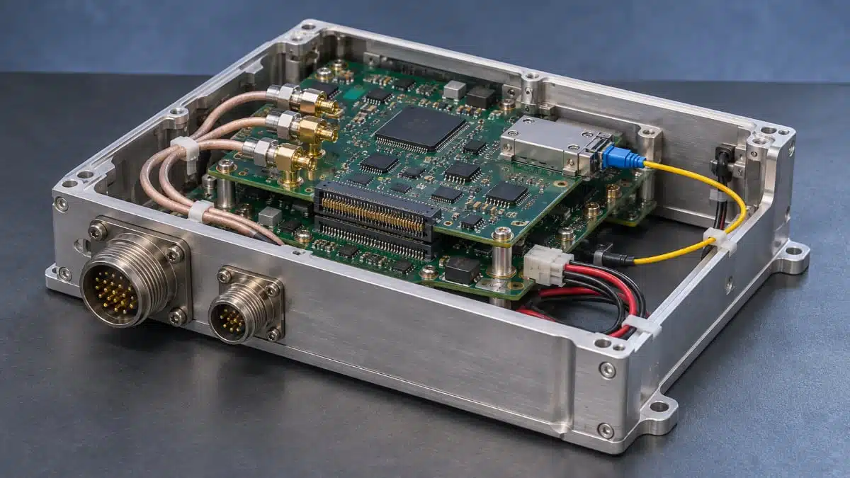
Military and aerospace interconnect design must balance signal bandwidth, packaging density and electrical power with mechanical retention and environmental exposure.
The challenge spans board-to-board connections inside computing modules, RF paths in sensing equipment and optical links between distributed electronics. Selecting the interconnect architecture early helps align the electrical interface, mechanical assembly and qualification plan.
Application requirements shape the architecture
Size, weight and power constraints affect more than connector dimensions. Contact arrangement, board spacing, cable routing and retention hardware all contribute to the installed assembly.
The main interconnect functions differ:
- Board-to-board arrays connect processing, storage and interface electronics within an enclosure.
- RF connectors and coaxial assemblies carry antenna, radar and communications signals.
- High-speed copper cables provide connections between boards, panels and processing devices.
- Optical links connect distributed sensors, cameras and computing equipment.
- Power connectors support board-level and cable-connected power distribution.
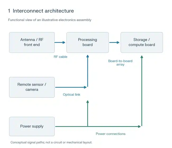
These functions can coexist within the same platform, but they require different selection criteria. A digital channel needs a defined signalling target and grounding arrangement. An RF path needs frequency-dependent performance. A power connection needs a current rating tied to its operating conditions.
The broader relationship between component selection, environmental stresses and lifecycle planning is covered in the aerospace and defense passive components dossier.
Technical highlights
Board density and signal allocation
Open-pin-field arrays allow contacts to be allocated to signals and grounds rather than imposing a fixed differential-pair arrangement. They can accommodate RF, analogue and digital connections within the same connector system.
Representative board-to-board configurations illustrate the available packaging choices:
| Configuration | Contact pitch | Contact count | Mechanical detail |
|---|---|---|---|
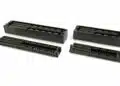
| SEAM/SEAF arrays | 1.27 mm | Up to 560 | 1.15 mm contact wipe |
| SEAM8/SEAF8 arrays | 0.80 mm | Up to 500 | Optional guide posts |
Pitch and contact count govern connection density, while contact wipe and guidance address mating mechanics. The pin map, grounding arrangement and board alignment therefore belong in the same design discussion.
Digital bandwidth and modular computing
Relevant interface targets include 25 Gbps channels, 56 Gbps PAM4 links and PCIe Gen 4 connections for storage and GPU clusters. These are distinct signalling requirements, not interchangeable connector ratings.
For modular embedded computing, VNX+ small-form-factor interconnect architecture provides an ANSI/VITA 90 framework covering more than the backplane connector. The family includes connector modules, power supply modules, cooling, mounting and retention, together with provisions for space applications.
This makes the module architecture an early decision. Connector selection, power delivery and mechanical retention need to fit the same framework rather than being resolved independently.
Optical links and environmental exposure
Mid-board optical transceivers support distributed data paths such as wing-mounted sensors connected to fuselage electronics, recording equipment connected to central computing and camera links within vehicles.
An extended-temperature optical system and an exposed-environment optical system address different installation conditions. For example, ETUO optical assemblies operate from −40 °C to +85 °C and use positive latching, weld tabs and loading guides. ETMO assemblies add sealing and Parylene coating for exposed installations, with environmental provisions covering salt fog, blowing sand and dust, and jet fuel exposure.
Operating temperature is therefore one selection axis; exposure protection is another. The enclosure location and cable route should guide the choice between them.
Typical applications and selection priorities
| Application | Interconnect functions | Main selection priorities |
|---|---|---|
| UAV electronics | Power, RF and data | Packaging, retention, cable routing |
| Radar equipment | RF and high-speed digital | Frequency range, grounding, channel performance |
| Avionics | Power, arrays and cable systems | Temperature, mating mechanics, environmental exposure |
| Distributed sensors and cameras | Optical data links | Link configuration, temperature, installation environment |
| Small satellites | Board, RF and optical connections | Outgassing, radiation, temperature, shock and vibration |
UAVs and distributed electronics
UAV assemblies combine power, RF and data connections under size and weight constraints. Mechanical latches, strain relief and guided mating should be considered alongside the electrical interface.
Distributed optical links introduce a different packaging problem: the transceiver, optical connector and cable route must fit the installation. A link between an exposed sensor and protected computing equipment may encounter different conditions at each end.
Radar and communications
Radar and communications equipment can combine precision RF paths with digital processing interfaces. RF selection should address the operating frequency and the behaviour of the cable assembly under temperature changes, flexure and repeated use.
For phased-array, signals-intelligence and electronic-warfare equipment, ganged RF interfaces provide multiple RF connections within one mating arrangement. The supported examples include 65 GHz interfaces on a 3.56 mm pitch.
Space electronics
Space applications add outgassing and radiation requirements to the thermal and mechanical assessment. These requirements need separate treatment in the selection plan.
The choice between commercial off-the-shelf hardware, modified hardware and additional screening should follow the mission requirements. The practical considerations behind this approach are explored in selecting COTS components for space applications.
Select the complete connection
Electrical performance, mating geometry, environmental exposure and procurement requirements interact. Selecting a connector by pitch or nominal data rate alone does not resolve the complete connection.
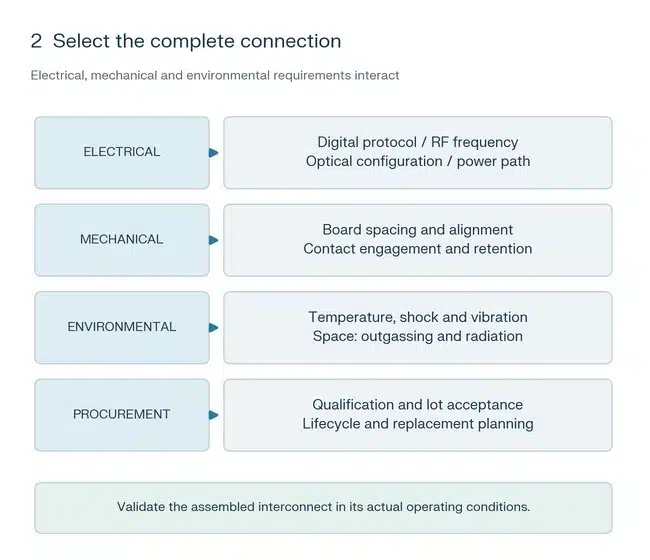
The selection process should establish the required interface and installation conditions before the PCB layout and enclosure design become fixed. Qualification and lot-acceptance requirements also belong in this early assessment because they influence the procurement specification.
Qualification and screening serve different purposes
Design qualification, additional environmental testing and production-lot screening address different questions.
Design qualification testing covers characteristics such as mating force, insulation resistance, dielectric withstand, current-carrying capacity, contact resistance, shock and vibration. Extended-life testing adds exposure and durability assessments, including mixed flowing gas and repeated mating.
Severe-environment testing adds further environmental stresses. Representative test conditions include:
| Assessment | Test condition |
|---|---|
| Mechanical shock | 40 g peak, 11 ms, half-sine |
| Random vibration | 12 g RMS, 5–2,000 Hz, 1 hour per axis |
| Temperature cycling | 500 cycles |
| Dielectric withstand at altitude | 70,000 ft |
These conditions are test parameters, not a single combined operating envelope.
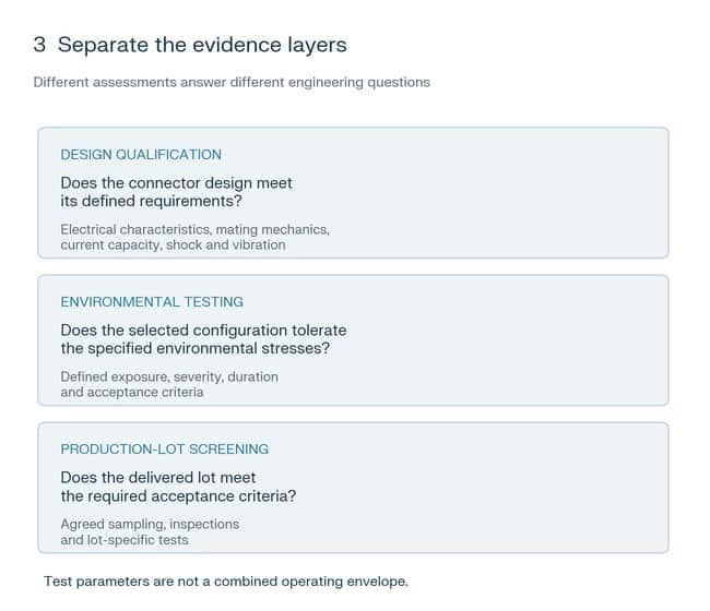
Lot screening addresses the supplied production lot. A military/aerospace product route can include customer-defined sample-size testing modelled on MIL-DTL-55302, together with manufacturing-location and product-specification controls.
Procurement requirements should therefore distinguish the qualified design, the required environmental tests and the acceptance criteria for delivered lots.
Design-in notes for engineers
- Define the interface requirement before choosing the connector: digital protocol, RF frequency range, optical configuration or power path.
- Develop signal and ground assignments alongside the PCB routing plan, particularly for open-pin-field arrays.
- Include board spacing, contact engagement, alignment features and retention hardware in the mechanical layout.
- Match optical packaging to the installation environment, including temperature and exposure to fluids or particulates.
- Separate design qualification, environmental testing and lot acceptance requirements in the procurement specification.
- Address manufacturing controls, replacement options and obsolescence management before production release.
- Validate the complete interconnect assembly under the actual electrical, thermal and mechanical operating conditions.
Further reading
Source
This article is based on the Samtec technical article and official product documentation. Engineers should refer to the current manufacturer datasheet for final design and qualification.
References
- Interconnecting Military and Aerospace Applications, Samtec, November 9, 2026.
- Military & Aerospace Connectivity Solutions, Samtec, October 2023
- What is VNX+, the New Standard for Small Embedded Designs?, Samtec, July 20, 2026.