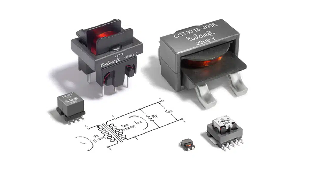
This blog is based on Coilcraft application article on selecting the best off-the-shelf current sense transformer for monitoring power supply current.
Current Sense Transformer Background
Accurate in-circuit current measurements are often required to limit over-current, optimize circuit performance, and control power circuits. Designers often
use current transformers to measure high-frequency changing (alternating) current of various waveforms, including continuous and discontinuous sinusoidal, triangular, trapezoidal, rectified, or pulsed current in the 1 to 100+ Amp range, while also providing galvanic isolation.
Isolation prevents ground loops and is required in high-voltage circuits to avoid noise interference between control networks and power circuits. Current transformers are frequently used in switched-mode power supply (SMPS) control systems to monitor average or peak current as required for operation and
circuit-protection decisions.
Current transformers sense high current levels while dissipating less power than resistive sensing methods and they can be used at higher frequencies, exceeding 1 MHz. The usable frequency range depends on the sensitivity of the circuit to measurement error and phase angle at the frequency of interest. For this discussion, turns ratio is the secondary-to-primary turns ratio (sec : pri), therefore “higher turns ratio” indicates higher secondary turns. Current transformers are typically offered in a range of turns ratios, with the higher turns ratios achieving a better signal-to-noise ratio in the control circuit than resistive sensing.
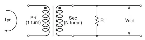
Current-sense transformers create an alternating current in the secondary winding that is proportional to the current passing through the primary winding. The current in the secondary is converted by a “burden” resistor – or terminating resistor (RT) – to a low voltage that can easily be measured in circuit.
A typical off-the-shelf current sense transformer has a 1-turn primary and a high-turns secondary. Alternating current passing through the primary winding creates a magnetic field that is coupled to the secondary. This field develops a voltage across the secondary and RT. With a 1-turn primary, the voltage drop (Vout) across RT is proportional to the current through the primary (Ipri) according to this equation:
Vout = (Ipri x RT) / Nsec
, where Nsec is the number of secondary winding turns. Therefore, selection of the terminating resistance is important in setting the correct maximum output voltage corresponding to the maximum expected primary current.
Resetting the Core
A diode in series with the secondary winding of a current transformer will set the core flux to zero after each cycle. This is advised in applications with high
duty cycle. The diode creates a voltage across the secondary to reset the transformer core while isolating that voltage from the control circuit. A Zener diode may also be employed to prevent overvoltage across the secondary. Without the diode to reset the core, flux will build up with each cycle, leading to core saturation that would make the sensed current appear to be lower. A lower sensed current would instruct the controller to increase current even further, which could destroy the circuit.
Current Transformer Accuracy
The accuracy of current transformers is defined as a %error in terms of the droop in the current waveform as it appears on the secondary. The %error calculation depends on the transformer characteristics and the operating conditions. Subsequently, it is not a set value for a given transformer. For a current pulse (or ramp),
%error = ( Imax / Isec) x 100
, where Imax is the maximum value reached at the end of the pulse and Isec is the secondary magnetizing current ( Ipri / Nsec ). This equation assumes the nominal value of the secondary magnetiz ing inductance, which typically has a ±20% tolerance. Therefore, %error may be defined as a range or worst case value at a specific primary current.
Balancing Design Requirements
Even with the best designs, the laws of physics enforce practical limits on design goals. For engineers, this means there may be trade-offs in component size,
current handling, and efficiency. Design optimization involves balancing these sometimes-competing parameters such that all design goals are met while achieving the best of each critical requirement.
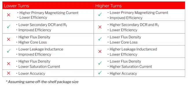
Off-the-shelf current transformers are typically available in a range of turns ratios for each package size. The effects of selecting a lower turns ratio vs. a higher-turns ratio is summarized in Table 1, which assumes a selection from an off-the-shelf series with the same package size for all choices within the series. The maximum sensed current rating is the same for all turns ratios within the series. This analysis also assumes that each RT is chosen to give 1 V output per 1 A input for the selected turns ratio. Doing so gives the best possible frequency bandwidth due to source-to-load impedance match.
A higher turns ratio in the same package size results in a higher secondary and RT resistance, which decreases efficiency. However, inspection of the Vout equation shows that a higher turns ratio requires a lower primary magnetizing current for the same Vout, which improves efficiency. A higher turns ratio (higher secondary turns) also means lower flux density, which leads to lower core loss, while the higher leakage inductance of a high turns ratio leads to higher core loss and lower efficiency.
When sensing high current, the saturating flux density of the core must be high enough to avoid core saturation. This requires a large-enough core size and sufficient turns count, both of which oppose a smaller part size requirement. Well-designed current transformers balance the need for the smallest size and the highest possible efficiency, while avoiding saturation at the intended operating current and frequency. The typical combination of low Vout and high secondary turns leads to low flux density, therefore, core saturation is typically not a concern with off-the-shelf current transformers. A higher turns ratio results in higher accuracy, while also creating a lower flux density, which helps prevent saturation and lowers core loss to help improve efficiency.
Application Examples Utilizing Current Transformers
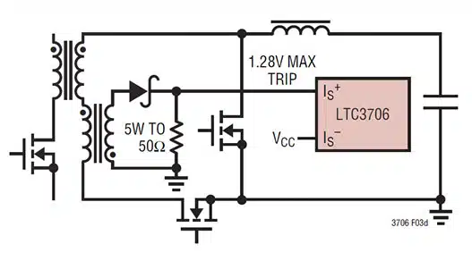
Analog Devices’ LTC3706 application note (ref. page 15) compares the use of current transformers vs resistive sensing methods to sense high current with the greatest efficiency. Figure 3d of the application note (Figure 2. below) illustrates current being sensed in the secondary winding of the isolation transformer using a current sense transformer with the LTC3706 Secondary-Side Synchronous Forward Controller.
The Texas Instruments TIDM-02009 ASIL D safety concept-assessed, high-speed traction, bi-directional DC-DC conversion reference design for HEV/EV applications uses two Coilcraft CST2010-100L current transformers. The bi-directional DC-DC converter module is designed to charge a low voltage (12 V) battery from a high voltage (400/600 V) battery bus when operated in the forward direction, and to pre-charge the DC bus capacitor in the reverse direction.
The DC-DC converter uses a peak current mode control (PCMC) technique. Coilcraft’s CST2010-100L current transformer has a 1 : 100 turns ratio and is used for primary inductance current sensing for the PCMC control.
Current Transformer Selection
Selecting the appropriate off-the-shelf current sense transformer for an application begins by determining:
- The maximum current to be sensed
- The frequency of the current waveform to be sensed
- The duty cycle of the current waveform to be sensed
- The desired output voltage across the terminating resistor
Coilcraft’s Current Transformer Finder tool simplifies the selection process significantly. This online resource helps you find the best current transformer for your application quickly, and includes behind-the-scenes flux density calculations to assure your selection is sized correctly to avoid core saturation. Coilcraft’s Selecting Current Sensors and Transformers application note also discusses the technology and application of current transformers.
Conclusion
Selecting the best off-the-shelf current sense transformer for monitoring power supply current has its challenges. These challenges can be met by understanding the design trade-offs in part size, efficiency, and accuracy. Selection is greatly simplified by online selection tools such as Coilcraft’s Current
Transformer Finder tool.
References
- Current Sense Transformer Calculation and Application
- Bob Mammano, “Current Sensing Solutions for Power Supply Designers”, Topic 1, SEM-1200, 1997, SLUP114
- Texas Instruments, “UCC28070 Interleaving Continuous Conduction Mode PFC Controller”, 2007, 2016, SLUS794F (starting on page 32)