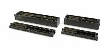





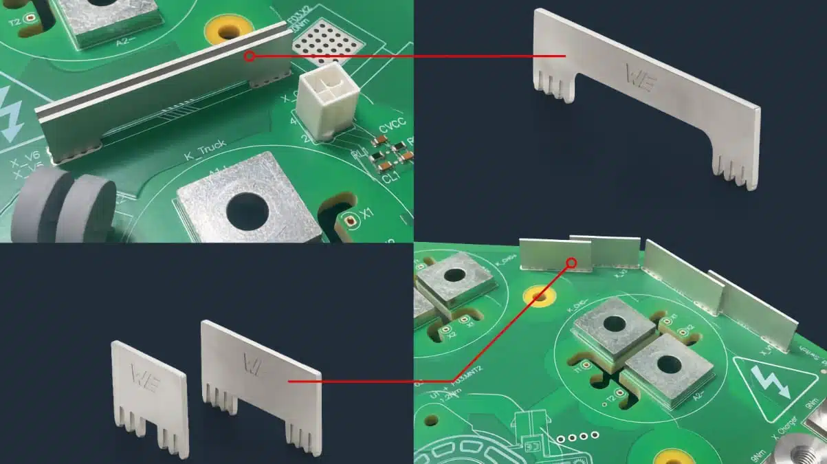
Würth Elektronik ICS has introduced PowerBusbar PF, a family of vertical press-fit busbars for distributing high currents across standard FR4 printed circuit boards.
Four standard lengths support local reinforcement of current paths and bridging over PCB regions, placing additional conductor cross-section where the circuit needs it rather than throughout the board.
Key features and benefits
- Four standard lengths: 19 mm, 29 mm, 39 mm and 59 mm.
- Copper-alloy construction with a tin surface.
- A 1.2 mm material thickness and 13.6 mm installed height above the PCB.
- Solder-free installation using solid press-fit PCB connections.
- Modular routing: multiple busbars can form a continuous high-current path.
- Vertical conductor surfaces provide a heat-conduction path and can act as cooling fins.
- High-current bridge configurations allow routing across PCB regions where a direct trace path is impractical.
Technical highlights
Standard sizes and ordering references
Würth Elektronik PowerBusbar PF is available in four standard sizes. The overall 18.4 mm dimension includes the pin section; the installed height above the PCB is 13.6 mm. This distinction matters when allocating enclosure space and checking assembly clearances.
| Part number | Length | Overall height | Thickness |
|---|---|---|---|
| K903583 | 19 mm | 18.4 mm | 1.2 mm |
| K903584 | 29 mm | 18.4 mm | 1.2 mm |
| K903585 | 39 mm | 18.4 mm | 1.2 mm |
| K904252 | 59 mm | 18.4 mm | 1.2 mm |
The pins are 4.8 mm long with a 2.0 mm diagonal. The busbars are intended for FR4 boards with a thickness starting at 1.5 mm.
Current capacity and thermal behaviour
Current capacity is a system-level property. It depends on the PCB layout, the busbar arrangement and thermal management, rather than the selected busbar length alone.
The vertical copper-alloy body carries current and conducts heat away from loaded board regions. At an ambient temperature of 40 °C and a current of 185 A, a measured temperature reduction of up to 53.5 K demonstrates the thermal contribution possible in a particular assembly. The 185 A measurement point is not a universal current rating for every PowerBusbar PF configuration.
Local reinforcement can allow a standard FR4 board to replace a heavy-copper or copper-inlay construction when the additional conductor cross-section is needed in specific regions. The design decision therefore concerns the complete current path and its thermal behaviour, not simply the board’s nominal copper thickness.
Press-fit assembly parameters
The busbars are designed for pressing into plated PCB holes; soldering is not an intended assembly process. Installation therefore adds no soldering-related thermal exposure at the busbar connection.
| Parameter | Value |
|---|---|
| PCB material | FR4 |
| Minimum PCB thickness | 1.5 mm |
| Installed height above PCB | 13.6 mm |
| Pin length | 4.8 mm |
| Pin diagonal | 2.0 mm |
| Press-in force | 60–250 N per pin |
| Retention force | 60–80% of press-in force |
| Press-in speed | 100–250 mm/min |
The PCB requires support during insertion, with the pressing force applied perpendicular to the board. Assembly options include a dedicated PowerBusbar PF tool or a press-fit template used with a standard press-fit tool. Suitable tooling also permits several busbars to be inserted simultaneously.
PCB requirements and mechanical qualification
PCB construction must follow IPC-A-600 and the Würth Elektronik ICS solid press-fit requirements. Drill diameter and through-hole copper thickness are central process parameters; the finished hole diameter alone is insufficient to define the press-fit interface.
PowerBusbar PF has passed random-vibration testing to IEC 60068-2-64 and mechanical-shock testing to IEC 60068-2-27.
Typical applications
Target applications include AI data centres, electric mobility, energy storage and industrial automation.
Within these systems, PowerBusbar PF supports two principal circuit positions:
- Local current-path reinforcement: the vertical conductor adds cross-section along a heavily loaded PCB route. The four standard lengths allow the reinforcement to follow different board regions.
- High-current bridging: the busbar carries current across a PCB area where direct routing on the board plane is impractical.
Multiple busbars can be combined to form longer or more complex current paths. Their vertical arrangement uses space above the board, making the 13.6 mm installed height a key mechanical selection parameter.
Design-in notes for engineers
- Select the busbar length together with the complete current route. Assess the PCB layout, busbar arrangement and thermal management as one system.
- Reserve the 13.6 mm above-board envelope and account for the 4.8 mm pin geometry in the mechanical stack-up.
- Define the drill and plating requirements with the PCB supplier before layout completion. Use the PowerBusbar PF press-fit interface requirements rather than a generic plated-hole fit.
- Provide board support and tool access. Apply the insertion force perpendicular to the PCB and keep the process within the 60–250 N per-pin force and 100–250 mm/min speed ranges.
- Plan a press-fit assembly operation rather than a soldering operation.
- Validate the final current path, temperature distribution and mechanical assembly under actual operating conditions before production release.
Further reading
- Würth Elektronik Releases 250A Threaded Press-Fit Connections
- Exxelia Releases High Performance Busbars for Power Electronics
Source
This article is based on the Würth Elektronik ICS product announcement and official product documentation. Engineers should refer to the current manufacturer datasheet for final design and qualification.
References
- PowerBusbar PF — Product Overview, Version 1.0, Würth Elektronik ICS.
- Vertical busbars enable high currents on standard PCBs, Würth Elektronik ICS, 2 November 2026.