Passive Components Blog
No Result
View All Result
  • Home
  • NewsFilter
    • All
    • Aerospace & Defence
    • Antenna
    • Applications
    • Automotive
    • Capacitors
    • Circuit Protection Devices
    • electro-mechanical news
    • Filters
    • Fuses
    • Inductors
    • Industrial
    • Integrated Passives
    • inter-connect news
    • Market & Supply Chain
    • Market Insights
    • Medical
    • Modelling and Simulation
    • New Materials & Supply
    • New Technologies
    • Non-linear Passives
    • Oscillators
    • Passive Sensors News
    • Resistors
    • RF & Microwave
    • Telecommunication
    • Weekly Digest

    Murata to Decouple China Rare Earth Supply in 3 Years

    Samtec AcceleRate Slim ARC6 Cable Assemblies with New Signaling Options

    Hirose Electric to Establish Automotive Connector Plant in India

    Schematic illustration of the electric double layer of porous carbon electrodes at elevated potentials in a a conventional electrolyte and b a weakly solvating electrolyte; source: authors

    Researchers Presented Lignin-based Electrolyte for 4V Supercapacitors with Low Self‑Discharge

    Samsung Outlines Growth Roadmap at its 52nd General Shareholders Meeting

    Samsung Electro-Mechanics Enters LEO Satellite Market With High‑Reliability MLCCs

    Vishay Introduced Space-Grade SMT Common Mode Choke

    Exxelia to Exhibit at APEC 2026 in San Antonio, Texas

    Würth Elektronik Presents Differential Pressure Sensor for HVAC and Medical

    Trending Tags

    • Ripple Current
    • RF
    • Leakage Current
    • Tantalum vs Ceramic
    • Snubber
    • Low ESR
    • Feedthrough
    • Derating
    • Dielectric Constant
    • New Products
    • Market Reports
  • VideoFilter
    • All
    • Antenna videos
    • Capacitor videos
    • Circuit Protection Video
    • Filter videos
    • Fuse videos
    • Inductor videos
    • Inter-Connect Video
    • Non-linear passives videos
    • Oscillator videos
    • Passive sensors videos
    • Resistor videos

    Thermal Modeling of Magnetics

    Standard vs Planar LLC transformers Comparison for Battery Chargers

    How Modern Tools Model Magnetic Components for Power Electronics

    Advanced Loss Modeling for Planar Magnetics in the Frenetic Planar Tool

    2026 Power Magnetics Design Trends: Flyback, DAB and Planar

    Enabling Software‑Defined Vehicle Architectures: Automotive Ethernet and Zonal Smart Power

    Calculating Resistance Value of a Flyback RC Snubber 

    One‑Pulse Characterization of Nonlinear Power Inductors

    Thermistor Linearization Challenges

    Trending Tags

    • Capacitors explained
    • Inductors explained
    • Resistors explained
    • Filters explained
    • Application Video Guidelines
    • EMC
    • New Products
    • Ripple Current
    • Simulation
    • Tantalum vs Ceramic
  • Knowledge Blog
  • DossiersNew
  • Suppliers
    • Who is Who
  • PCNS
    • PCNS 2025
    • PCNS 2023
    • PCNS 2021
    • PCNS 2019
    • PCNS 2017
  • Events
No Result
View All Result
Passive Components Blog
No Result
View All Result

How to Design High Energy Power Inductor

29.11.2022
Reading Time: 9 mins read
A A

This article written by Dr. Chema Molina, Frenetic is continuation of his series of articles about Magnetics Design started by the article How to design an inductor.

In the first article, I designed a DC inductor with Ferrite material.

RelatedPosts

Thermal Modeling of Magnetics

Standard vs Planar LLC transformers Comparison for Battery Chargers

How Modern Tools Model Magnetic Components for Power Electronics

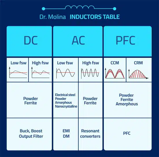
As you can see in My table of Inductors in Figure 1., the most common materials for DC inductors are ferrite and powder. In this article, I will focus on a higher energy inductor using Powder material.

The powder manufacturer I use to work with is Magnetics. They also recommend Frenetic as an external tool, however, they provide enough information to help you in the design process at this link (https://www.mag-inc.com/Design/Technical-Documents/Powder-Core-Documents).

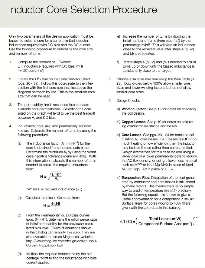
Magnetics provides you with an algorithm to design an inductor with their catalog.

Figure 1. Dr. Molina Inductors Design Table
Figure 2. Inductor core selection procedure; source: Magnetics

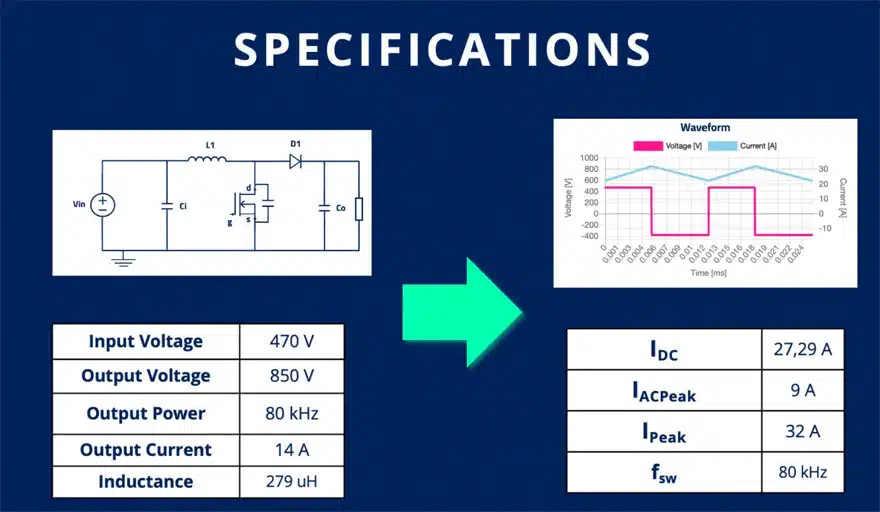
Case Study How to Design High Energy Power Inductor – 12,5 kW Boost Converter

The specs of the inductor we will use as a case study are based on the WOLFSPEED application note of a 4 phases boost converter of 60 kW, 12,5 kW for each phase.

Figure 3. Case Study Specifications How to Design High Energy Power Inductor – 12,5 kW Boost Converter

Following the Magnetics algorithm

The first step is to calculate the total energy:

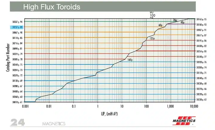
With this value, we will choose a magnetic core and material. Each material will offer you a different balance between energy stored and inductance stability. I choose High Flux.

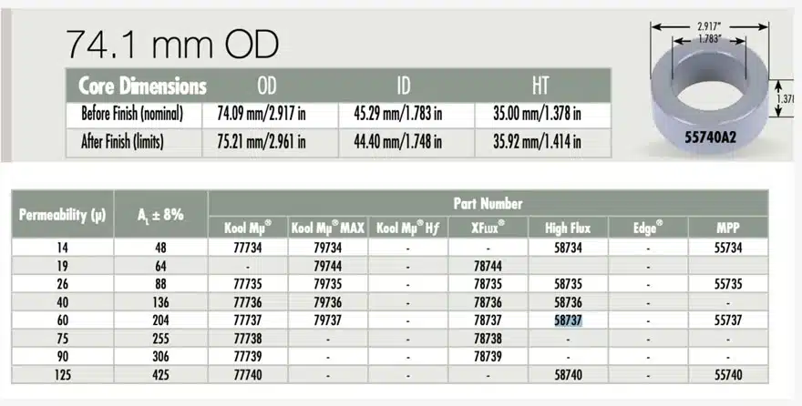
 In the material graph, you have to choose the part which has a higher value than the energy calculated before. As you can see in the picture below, for this case, we are choosing part 58737.

Figure 4. High Flux Toroids Energy Specification Chart

In the same catalog, we can go to check the parameters of this core. On this page, you can find the physical description of the component and the permeability values as well as some support for the winding process regarding the window area.

Figure 4. High Flux Toroids Specification Table

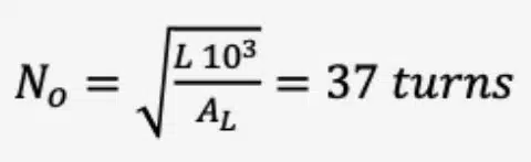
With the material selected, we have to calculate the number of turns for the selected core:

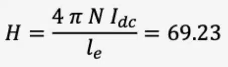
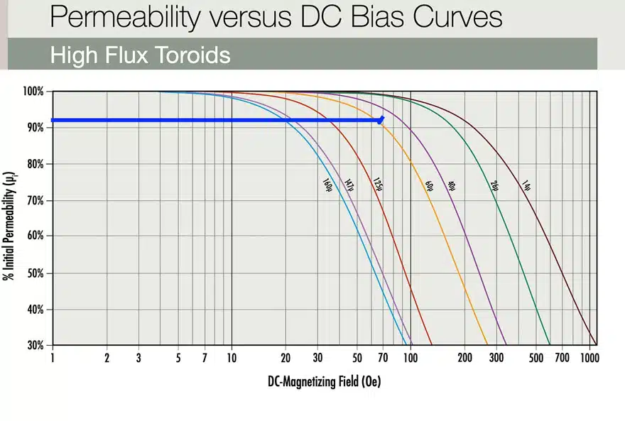
This is the first approximation, now, we have to ensure the inductance required at the DC current, because with this material the inductance decrease with the DC current. For this purpose, we will calculate the H:

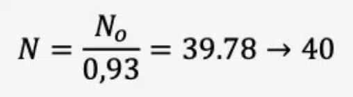
Then, we go to the permeability versus DC bias (H) curves for this material and we can find the percent to correct the number of turns – see Figure 5. In this particular case for H= 68.6, the % of permeability is 93%.

Figure 5. Permeability versus DC bias (H) curves

With 93% we can recalculate the number of turns:

If you want to know the value of the inductance for each DC current, you can create a function to calculate each point.  For a boost converter, the most important is to be sure, the minimum inductance won´t increase the output ripple out of your limits.

Now, we have the core and the turns, the algorithm of magnetics proposes we choose the AWG wire to meet a maximum of 5A/mm2 . This is quite simple, with the 27,4 A of DC current, the minimal area of the wire should be:

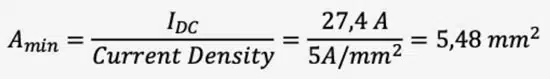
Following this rule, we will choose between AWG 9 or 10. However, these wires could be very wide and difficult to manage. I would recommend choosing a thinner one and putting some wires in parallel. In my case, I have chosen AWG 12 and 2 parallel wires.

You need to check the window area, to ensure that the number of turns with your specific diameter will fit in the area available. In this case, I’m using 21.9% of the space. The maximum space is relative to a lot of factors but as a rule of thumb, I would say 60% is the limit.

As you can see, in this process we have calculated any losses or talked about proximity due to winding configuration. In the Magnetics document, there is support to calculate the losses, however, from my point of view, it’s complex and it could produce a lot of human errors in the process.

Therefore, the design is completed. I have checked the losses using Frenetic because their proposal is very simple. The total losses are 12,5W

Design using Frenetic

When I started building this product, I reviewed my old process and asked myself, what would help me a lot in the process?

I had three requests:

1.    Automatic inductance calculation

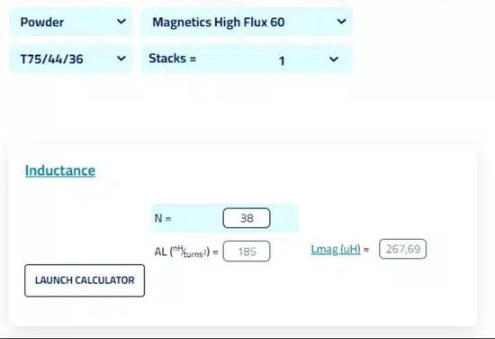
Automatic inductance calculation for each DC bias and all the materials to avoid checking one by one graph and calculating the number of turns in an iterative mode. Therefore, this is our inductance calculator – see Figure 6. Where calculating the inductance for any magnetic core, for any DC inductance is just a matter of seconds. Here, I can calculate the number of turns for each core or most important. Multiple Stacks of cores.

Figure 6.  Calculating the inductance for any magnetic core; Frenetic calculator
Figure 7.  Inductance with current dependance; source: Frenetic

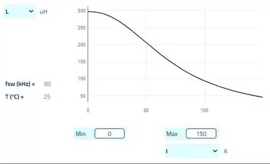
2.    Automatic Curves for each material

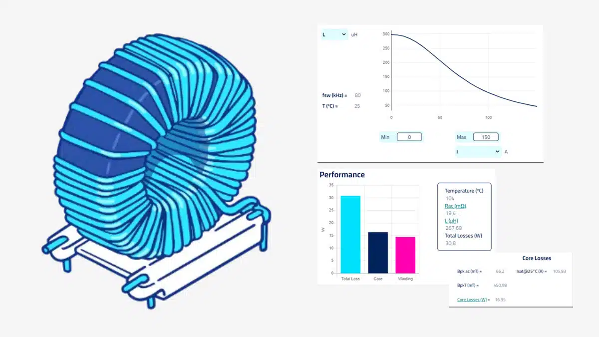
The inductance depends on the current, with this curve, I can see the whole behavior of the component – See Figure 7.

3.    Losses & Saturation

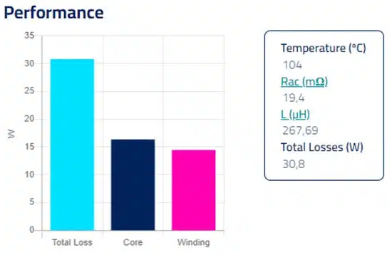
With an automatic losses calculation, I can compare different designs, considering losses in the core and the winding. As well as using litz wires, and calculating proximity losses for high-frequency applications with several layers – see Figure 8.

Something to have in mind during a design is the saturation current. To avoid problems with current peaks which could saturate the system, Frenetic provides automatically the saturation current – see Figure 9.

Figure 8. Inductor losses components evaluation; source: Frenetic
Figure 9. Inductor losses and saturation current calculation; source: Frenetic

Related

Source: Frenetic

Recent Posts

Schematic illustration of the electric double layer of porous carbon electrodes at elevated potentials in a a conventional electrolyte and b a weakly solvating electrolyte; source: authors

Researchers Presented Lignin-based Electrolyte for 4V Supercapacitors with Low Self‑Discharge

19.3.2026
2

Vishay Introduced Space-Grade SMT Common Mode Choke

19.3.2026
4

Exxelia to Exhibit at APEC 2026 in San Antonio, Texas

17.3.2026
26

Thermal Modeling of Magnetics

16.3.2026
11

ESA SPCD 26 Call for Papers Extended to 30th March

16.3.2026
80

Panasonic Releases Transparent EMI Shielding Film for Displays

16.3.2026
16

Standard vs Planar LLC transformers Comparison for Battery Chargers

13.3.2026
26

Bourns Expanded Semi-Shielded Low Profile Automotive Power Inductor

12.3.2026
16

Panasonic Extends Automotive Power Inductor Line

9.3.2026
31

Upcoming Events

Mar 19
13:00 - 14:00 CDT

Smart Consideration of Inductor Thermal Performance

Mar 21
All day

PSMA Capacitor Workshop 2026

Mar 24
9:00 - 10:00 CET

Power protection in the digital age – eFuse and hot-swap strategies for modern data center design

View Calendar

Popular Posts

  • Buck Converter Design and Calculation

    0 shares
    Share 0 Tweet 0
  • Boost Converter Design and Calculation

    0 shares
    Share 0 Tweet 0
  • Flyback Converter Design and Calculation

    0 shares
    Share 0 Tweet 0
  • LLC Resonant Converter Design and Calculation

    0 shares
    Share 0 Tweet 0
  • MLCC Manufacturers Consider Price Increase as AI Demand Outpaces Supply

    0 shares
    Share 0 Tweet 0
  • Dual Active Bridge (DAB) Topology

    0 shares
    Share 0 Tweet 0
  • MLCC and Ceramic Capacitors

    0 shares
    Share 0 Tweet 0
  • Ripple Current and its Effects on the Performance of Capacitors

    3 shares
    Share 3 Tweet 0
  • MLCC Case Sizes Standards Explained

    0 shares
    Share 0 Tweet 0
  • 3-Phase EMI Filter Design, Simulation, Calculation and Test

    0 shares
    Share 0 Tweet 0

Newsletter Subscription


Passive Components Blog

© EPCI - Leading Passive Components Educational and Information Site

  • Home
  • Privacy Policy
  • EPCI Membership & Advertisement
  • About

No Result
View All Result
  • Home
  • Knowledge Blog
  • PCNS

© EPCI - Leading Passive Components Educational and Information Site

This website uses cookies. By continuing to use this website you are giving consent to cookies being used. Visit our Privacy and Cookie Policy.
Go to mobile version