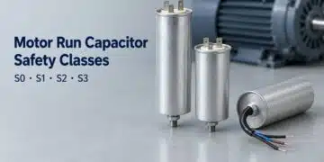



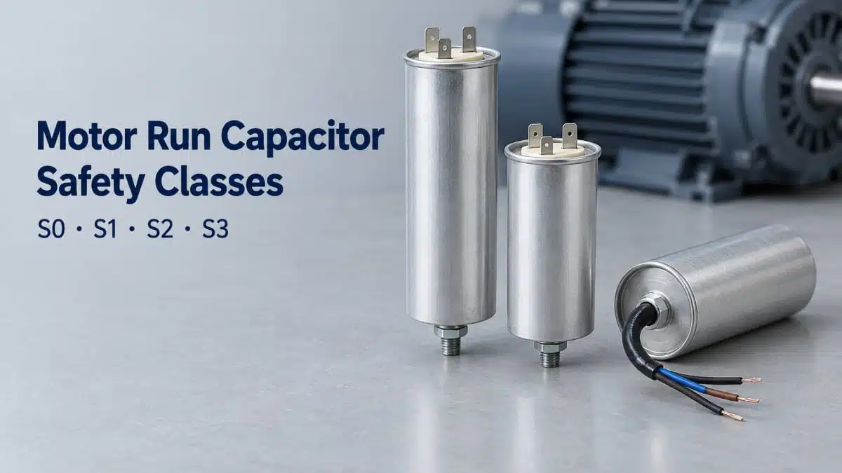
Motor run capacitor selection involves more than capacitance, voltage and operating life: the equipment must also accommodate what happens when the capacitor fails. Self-healing, overpressure disconnection and segmented electrodes address different aspects of that problem.
This technical paper is an edited and extended adaptation of the HYDRA white paper “Motor Run Capacitor Safety Classes S0 to S3: How to Specify Failure Protection under IEC 60252-1”. It connects the protection mechanisms and test requirements to electrical selection, mechanical integration and equipment qualification.
Background and design challenge
A motor run capacitor’s safety class defines its degree of protection during failure. It does not establish capacitance accuracy, normal operating performance or probable life. This distinction matters in appliances, pumps, compressors and fans. A capacitor may recover from individual dielectric breakdowns yet eventually lose capacitance, develop an internal fault or generate heat and gas. The equipment’s safety concept must account for the resulting electrical and mechanical behaviour.
The selection problem therefore has three separate parts:
- Choose the electrical characteristics required by the motor.
- Choose the operating-life and environmental classifications required by the duty.
- Choose the failure-protection class required by the equipment.
The class marking cannot replace the other two decisions. Equally, a suitable voltage rating and life class do not establish the required failure behaviour.
IEC 60252-1: scope and terminology
IEC 60252-1 covers capacitors connected to the windings of asynchronous motors supplied from a single-phase system at frequencies up to and including 100 Hz. It also covers capacitors used to operate three-phase asynchronous motors from a single-phase supply.
Its scope includes rated voltages up to and including 660 V. The dielectric may be paper, plastic film or a combination, with metallized or metal-foil electrodes. The consolidated edition 2.1 combines the second edition of 2010 with Amendment 1 of 2013. European adoption is EN 60252-1:2011 + A1:2013; German adoption is DIN EN 60252-1 (VDE 0560-8):2014-07.
Related capacitor standards
The intended circuit position determines which component standard applies:
- IEC 60252-2 covers motor start capacitors.
- IEC 60831-1 covers shunt capacitors for AC power systems up to 1,000 V.
- IEC 61071 covers capacitors for power electronic circuits.
- IEC 61048 covers small AC capacitors for fluorescent and discharge lamps.
Motor run capacitor classifications should therefore be interpreted within their defined application, rather than transferred to other capacitor categories.
Earlier P-class markings
Older documentation may use P0, P1 and P2 for the classes now designated S0, S1 and S2. S3 has no former P designation. The 2010 edition added the definition of segmented capacitors in clause 3.6. Amendment 1 of 2013 established the separate destruction-test approach for S3 segmented-film construction.
What the four safety classes mean
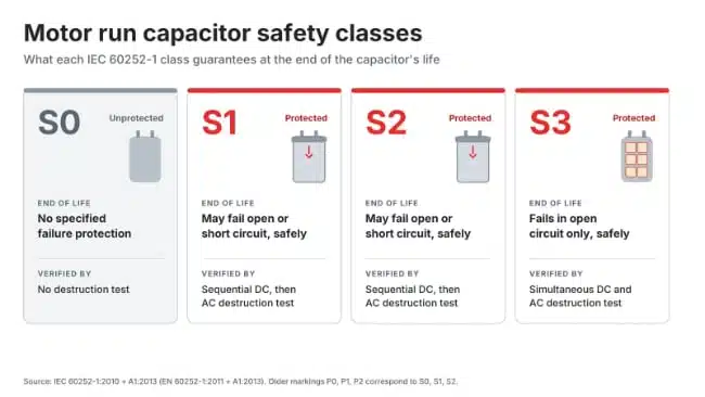
Definition 3.22 and subclause 5.16.1 connect each protected class to its failure behaviour and destruction-test procedure.
| Class | Failure behaviour | Protection construction | Destruction test |
|---|---|---|---|
| S0 | No specific failure protection | Not prescribed | Not required |
| S1 | Open or short circuit | Overpressure disconnector | Sequential DC and AC |
| S2 | Designed for open circuit | Overpressure disconnector | Sequential DC and AC |
| S3 | Residual capacitance <1% | Segmented film | Simultaneous DC and AC |
S1 and S2 include protection against fire or shock hazard. S3 includes protection against fire and shock hazard.
S0: equipment-level protection
S0 means the capacitor type has no specific failure protection. Protection against the consequences of its failure therefore resides in the surrounding equipment. This is a system-design decision. The class does not establish a built-in disconnection mechanism.
S1 and S2: different permitted failure modes
S1 and S2 undergo the same sequential destruction test. Their distinction is the permitted failure mode. An S1 capacitor may fail in either the open-circuit or short-circuit mode. An S2 capacitor is designed to fail in the open-circuit mode. Where the equipment requires open-circuit failure, the distinction is consequential even though the two classes share a test sequence.
S3: low residual capacitance
S3 combines segmented-film construction with a residual-capacitance requirement below 1% of rated capacitance after failure. That criterion is different from the mechanical disconnection used in S2. S3 should not be interpreted as an operating-life grade above S2: the classes address failure protection through different constructions and test procedures.
Self-healing: how local dielectric recovery works
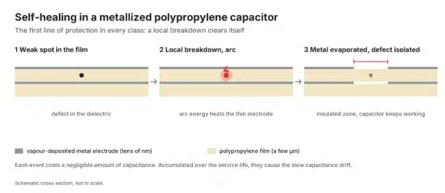
Metallized film capacitor construction places a thin electrode layer on the dielectric film. In the construction considered here, the metal layer is typically less than 100 nm thick.
When the polymer breaks down at a weak point, current flows through the defect. The current evaporates the surrounding metallization until the conductive path becomes isolated. The capacitor can then continue operating with a small reduction in capacitance. This is the physical basis of self-healing.
Recovery removes active electrode area
Each clearing event sacrifices a small area of electrode. As isolated defects accumulate, the active area decreases and capacitance falls.
Capacitance dropping below the required tolerance is a common end-of-life mechanism for metallized film capacitors. The relationship between clearing and capacitance loss is important when interpreting capacitor failure mechanisms: successful local recovery does not mean that the component retains its original capacitance indefinitely.
Self-healing is not complete failure protection
A failing capacitor can generate heat and gas, raising internal pressure. Severe failure can lead to fire or enclosure rupture. Self-healing addresses individual dielectric defects. Overpressure disconnectors and segmented construction add another protection mechanism for failure conditions. The engineering distinction is between recovery during operation and controlled behaviour at failure. Both matter, but they are not interchangeable.
Overpressure disconnection: electrical protection through movement
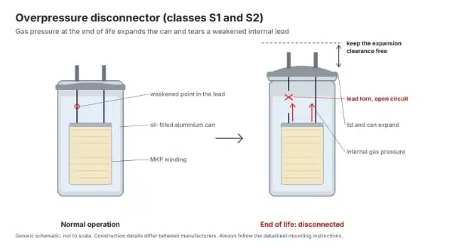
S1 and S2 capacitors use an overpressure disconnect device. During destructive failure, gas generation and increasing temperature raise pressure inside the enclosure. In HYDRA’s S2 construction, the can expands axially. That movement breaks a weakened section of an internal conductor and disconnects the capacitor from the mains. The sequence links electrical failure, pressure generation, enclosure movement and interruption of the current path.
Expansion clearance belongs in the mechanical specification
For HYDRA series 321, axial extension can reach approximately 9 mm when the disconnector operates. Approximately 12 mm clearance is required between the terminal and neighbouring components.
The two dimensions serve different purposes:
- Approximately 9 mm describes the possible axial movement.
- Approximately 12 mm describes the required installation clearance.
A normal operating envelope is therefore not the complete installation envelope. Positioning a neighbouring component against the terminal area can conflict with the movement needed by the protection mechanism. Case selection, terminal routing, mounting position and expansion clearance should be resolved together. The protection is not solely an electrical feature inside the capacitor.
The enclosure is part of the mechanism
Pressure-driven disconnection depends on pressure developing within a closed can. IEC 60252-1 includes a sealing test in clause 5.12. This connects enclosure integrity to the protection mechanism. The can is both a package and a mechanical element in the failure response.
Segmented film: protection built into the electrode
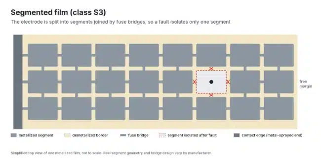
S3 construction places the protection concept within the metallization. The electrode is divided into metallic areas separated by non-metallic lines. This deliberate pattern differs from a continuous metallized electrode.
Segmentation and self-healing are different features
Self-healing removes metal around a dielectric defect after breakdown. Segmentation divides the electrode into areas as part of its original construction. The two terms therefore refer to different aspects of the capacitor:
- Self-healing concerns local isolation of a breakdown site.
- Segmentation concerns the electrode pattern.
- S3 classification combines segmented construction with a defined failure criterion and test method.
A self-healing description alone does not establish S3 classification.
What the residual-capacitance requirement means
The S3 failure criterion requires residual capacitance below 1% of rated capacitance, together with protection against fire and shock hazard. This is an end-of-failure acceptance criterion, not a normal operating tolerance or an allowable capacitance drift during service. It should also remain distinct from S2’s open-circuit design requirement. Both address failure, but one uses a residual-capacitance threshold and the other uses pressure-driven interruption. UL 810 likewise distinguishes segmented-film protection from expansion-type protection. The physical approach, rather than the class number alone, is central to understanding how the capacitor behaves.
Destruction tests and other qualification tests
IEC 60252-1 clause 5.16 covers destruction testing for S1, S2 and S3. The test is optional within the component standard. S0 capacitors are not required to undergo it. Capacitors designated S1, S2 or S3 are associated with their corresponding test procedures. The following descriptions concern standard test methods, not measured results from a particular product sample.
Sequential DC and AC testing for S1 and S2
S1 and S2 specimens first undergo DC conditioning and then an AC destruction test. The AC test circuit includes a variable inductor. Subclauses 5.16.3 and 5.16.5 cover this sequence. The shared procedure does not remove the distinction between the classes’ permitted failure modes.
Simultaneous DC and AC testing for S3
S3 capacitors undergo simultaneous DC and AC stresses under subclauses 5.16.4 and 5.16.6. Clause 5.16.7 governs the evaluation of failure. The different procedure reflects the different construction and failure criterion.
Destruction testing is one part of qualification
Other tests in IEC 60252-1 include:
- Sealing, clause 5.12.
- Endurance, clause 5.13.
- Damp heat, clause 5.14.
- Self-healing, clause 5.15.
- Resistance to heat, fire and tracking, clause 5.17.
The heat, fire and tracking section includes ball-pressure, glow-wire and tracking tests. Table 1 of the standard provides the type-test schedule. These tests address different properties. A destruction-test classification does not replace endurance, environmental or enclosure assessments.
Safety class, probable life and climatic category
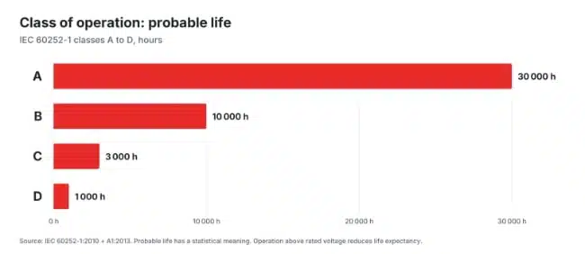
The safety class concerns failure protection. Class of operation concerns probable life. Climatic category defines temperature limits and damp-heat test severity.
All three belong in a complete specification.
| Class of operation | Probable life |
|---|---|
| A | 30,000 h |
| B | 10,000 h |
| C | 3,000 h |
| D | 1,000 h |
Since the 2010 edition, the class-of-operation definition includes probable life with reference to statistics. These values are not a substitute for the voltage and temperature conditions associated with the selected component. IEC 60252-1 clause 6.1 also establishes that operation above rated voltage reduces life expectancy.
Reading a combined product specification
HYDRA series 321 illustrates the separate entries:
| Parameter | Value |
|---|---|
| Rated voltage | 280 V AC |
| Frequency | 50/60 Hz |
| Class of operation | B: 10,000 h |
| Safety class | P2/S2 |
| Climatic category | 25/85/21 |
The climatic category corresponds to −25 °C lower temperature, +85 °C upper temperature and a damp-heat severity of 21 days under IEC 60068. These entries answer different questions. The voltage and frequency define electrical conditions; class B addresses probable life; S2 addresses failure protection; and the climatic category addresses environmental classification.
Choosing the safety class for an application
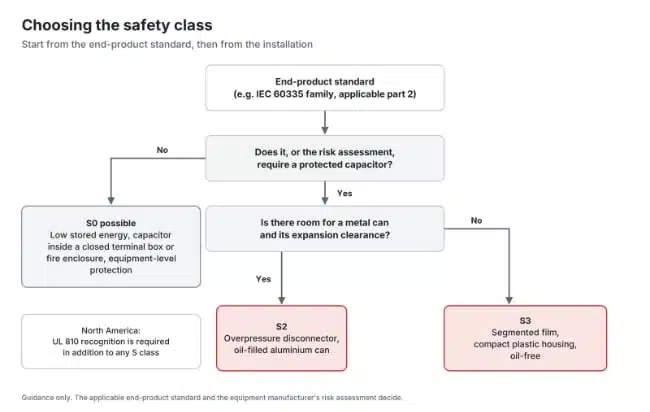
Selection starts with the end product and its installation. IEC 60252-1 does not impose one universal class for every motor application. The required class follows from the applicable equipment requirements and the intended response to capacitor failure.
Establish the end-product requirements first
Household and similar appliances with rated voltages up to 250 V single-phase or 480 V otherwise fall within the scope discussed under IEC 60335-1. IEC 60335-1 includes a normative Annex F on capacitors and references IEC 60252-1:2010. The applicable appliance requirements therefore belong ahead of catalogue selection.
For North America, UL 810 Part I covers enclosed capacitors with integral protection intended to reduce the risk of enclosure rupture and venting during internal faults. Applications include appliances, air-conditioning and refrigeration equipment, and motors. UL 810 is separate from IEC 60252-1. An IEC class marking and the approvals required for a destination market should be treated as separate specification entries.
Decide where failure protection resides
- For S0, protection against the consequences of failure resides in the equipment.
- For S1, the capacitor provides the associated protection but may fail open or short circuit.
- For S2, the capacitor is designed for open-circuit failure and requires the mechanical allowance needed by its overpressure disconnector.
- For S3, protection uses segmented film and the residual-capacitance criterion below 1%.
The decision is therefore not simply which class has the largest number. It is which construction and failure behaviour fit the equipment requirements.
Connect the class to the installation
Overpressure-protected parts require space for their mechanism to operate. Segmented-film protection uses a different physical approach, but does not remove the need to meet the selected part’s voltage, temperature, mounting and approval requirements.
Target applications include white goods, pumps, compressors, blowers, fans and ventilation equipment. The application name alone does not determine the class: equipment requirements and installation conditions govern the choice.
Design-in notes for engineers
- Capacitance and tolerance: match the motor manufacturer’s recommendation.
- Rated voltage: base selection on the working voltage measured at the capacitor terminals, as addressed in IEC 60252-1 clause 9.2.
- Frequency: establish whether the equipment operates at 50 Hz, 60 Hz or both.
- Class of operation: select probable life together with the component’s voltage and temperature conditions.
- Climatic category: assess capacitor temperature in the installed equipment, including the guidance associated with clause 9.3.
- Safety class: record S0, S1, S2 or S3 explicitly, together with the required failure behaviour.
- Approvals: include the destination-market requirements and the production site covered by the relevant certificates.
- Mechanical integration: define the case, terminals, mounting stud, cable length and mounting position. Include expansion clearance for overpressure-protected parts.
- Final validation: validate the complete selection under actual operating conditions before production release.
Conclusion
The safety class is a one-character field. S0 has no specific failure protection. S1 and S2 add an overpressure disconnect device verified by a sequential destruction test, and S2 is designed to fail in the open-circuit mode only. S3 relies on segmented film and must fail with a residual capacitance below 1 % of rated capacitance. State the class together with the class of operation and the climatic category, and treat the datasheet’s mounting and clearance instructions as part of the safety concept.
HYDRA motor run capacitors and documents
HYDRA motor run capacitors are made in two of the classes discussed above: S0 in a dry, resin-potted design and S2 with an overpressure disconnector. The datasheets state the mounting conditions that belong to the safety concept. For series 321, for example, the can may extend axially by up to about 9 mm when the disconnector operates, and a clearance of about 12 mm to neighbouring components is required.
| Series | Safety class | Rated voltage | Capacitance | Datasheet |
|---|---|---|---|---|
| 285 | S0 | 400 to 450 V AC | 0.8 to 30 µF | Series 285 (PDF) |
| 400 | S0 | 400 to 500 V AC | 0.8 to 40 µF | Series 400 (PDF) |
| 321 | S2 | 280 V AC | 1 to 100 µF | Series 321 (PDF) |
| 322 | S2 | 400 V AC | 2 to 20 µF | Series 322 (PDF) |
| 500 | S2 | 400 to 500 V AC | 1 to 80 µF | Series 500 (PDF) |
Further reading
- Film Capacitors Characteristics and Uses in Power Applications
- Power Film Capacitor Design for EV and HEV Applications
- Predicting Metal Film Capacitor Lifetime Using Thermal Simulation
Source
This technical paper is an edited and extended adaptation of the HYDRA white paper “Motor Run Capacitor Safety Classes S0 to S3: How to Specify Failure Protection under IEC 60252-1” (2026), published with the permission of HYDRA. Engineers should refer to the current manufacturer datasheets for final design and qualification.
References
- Motor Run Capacitor Safety Classes S0 to S3: How to Specify Failure Protection under IEC 60252-1, HYDRA, 6 October 2026; updated 16 October 2026.
- IEC 60252-1:2010+AMD1:2013 CSV — AC motor capacitors, Part 1: General—Performance, testing and rating—Safety requirements—Guidance for installation and operation, IEC, edition 2.1, 2013.
- EN 60252-1:2011/A1:2013 — AC motor capacitors, Part 1, CENELEC, 2013; SIST adoption, 2014.
- HYDRA Capacitors Catalogue 2025, HYDRA, 2025.
Technical Bibliography
- IEC 60252-1:2010+AMD1:2013 CSV, AC motor capacitors—Part 1: General—Performance, testing and rating—Safety requirements—Guidance for installation and operation. Consolidated edition 2.1. IEC, 2013.
- EN 60252-1:2011/A1:2013, corresponding to IEC 60252-1:2010/A1:2013. CENELEC, 2013. SIST EN 60252-1:2011/A1:2014 sample, iTeh Standards.
- EN 60252-1:2011, endorsement notice. CENELEC, 2011. SIST EN 60252-1:2011 sample, iTeh Standards.
- DIN EN 60252-1 (VDE 0560-8):2014-07, German version EN 60252-1:2011 + A1:2013. VDE VERLAG, 2014.
- IEC 60252-2:2010+AMD1:2013 CSV, AC motor capacitors—Part 2: Motor start capacitors. IEC, 2013.
- IEC 60335-1:2020, Household and similar electrical appliances—Safety—Part 1: General requirements. Edition 6.0. IEC, 2020.
- UL 810, Capacitors. Sixth edition, 2019; revised 2025. UL Standards & Engagement.
- R. Gallay, Metallized Film Capacitor Lifetime Evaluation and Failure Mode Analysis. CERN Yellow Reports, CERN-2015-003, p. 45. DOI: 10.5170/CERN-2015-003.45.
- H. Wang and F. Blaabjerg, Reliability of Capacitors for DC-Link Applications in Power Electronic Converters: An Overview. IEEE Transactions on Industry Applications, volume 50, issue 5, 2014.
- HYDRA motor capacitor datasheets, series 321 and series 285. HYDRA.