Passive Components Blog
No Result
View All Result
  • Home
  • NewsFilter
    • All
    • Aerospace & Defence
    • Antenna
    • Applications
    • Automotive
    • Capacitors
    • Circuit Protection Devices
    • electro-mechanical news
    • Filters
    • Fuses
    • Inductors
    • Industrial
    • Integrated Passives
    • inter-connect news
    • Market & Supply Chain
    • Market Insights
    • Medical
    • Modelling and Simulation
    • New Materials & Supply
    • New Technologies
    • Non-linear Passives
    • Oscillators
    • Passive Sensors News
    • Resistors
    • RF & Microwave
    • Telecommunication
    • Weekly Digest

    EMC‑Compliant PCB and Connector Design Guidelines

    Practical Value of Structural Diagnostics for Tantalum Capacitor Anodes

    Hall-Effect Sensing for Harsh Environments: TT Electronics Selected in NASA’s Dragonfly Fan

    Bourns Releases Automotive Gate Driver Transformer for Isolated Power

    Stackpole Releases High-Frequency Thin Film Chip Resistors for RF up to 50 GHz

    Knowles Expands High‑Q Ceramic Core Inductors for RF designs

    Vishay Unveils 1.5 kV IHDV High Voltage Power Inductors for EV and Industrial Converters

    SCHURTER Introduces PPTC Resettable Overcurrent Protection for Compact Electronics

    TrendForce: CSP in‑house AI ASIC Boom Reshapes Capacitor Demand

    Trending Tags

    • Ripple Current
    • RF
    • Leakage Current
    • Tantalum vs Ceramic
    • Snubber
    • Low ESR
    • Feedthrough
    • Derating
    • Dielectric Constant
    • New Products
    • Market Reports
  • VideoFilter
    • All
    • Antenna videos
    • Capacitor videos
    • Circuit Protection Video
    • Filter videos
    • Fuse videos
    • Inductor videos
    • Inter-Connect Video
    • Non-linear passives videos
    • Oscillator videos
    • Passive sensors videos
    • Resistor videos

    EMC‑Compliant PCB and Connector Design Guidelines

    Why Isolated DC/DC Power Supplies Fail Late, Würth Elektronik Podcast

    Designing 800 V DC EMC Filters: Calculation, Simulation and Measurement

    Current Sense Transformer Datasheet and Design‑in Guide

    Designing a USB Type‑C Flyback Planar Transformer with Frenetic’s Planar Tool

    Magnetics Design in High‑Frequency GaN Converters

    Qi2 Wireless Charging: Inductors, Capacitors and EMC Filters

    Two‑capacitor paradox explained for engineers

    Capacitances of Nonlinear MLCCs: What Datasheets Don’t Tell You

    Trending Tags

    • Capacitors explained
    • Inductors explained
    • Resistors explained
    • Filters explained
    • Application Video Guidelines
    • EMC
    • New Products
    • Ripple Current
    • Simulation
    • Tantalum vs Ceramic
  • Knowledge Blog
  • DossiersNew
  • Suppliers
    • Who is Who
  • PCNS
    • PCNS 2025
    • PCNS 2023
    • PCNS 2021
    • PCNS 2019
    • PCNS 2017
  • Events
No Result
View All Result
Passive Components Blog
No Result
View All Result

Vishay Edge-Wound Inductor Delivers Stable Inductance and Saturation at Temps to +180 °C and Current to 150 A

22.8.2019
Reading Time: 3 mins read
A A

Source: Vishay, Globe Newswire news

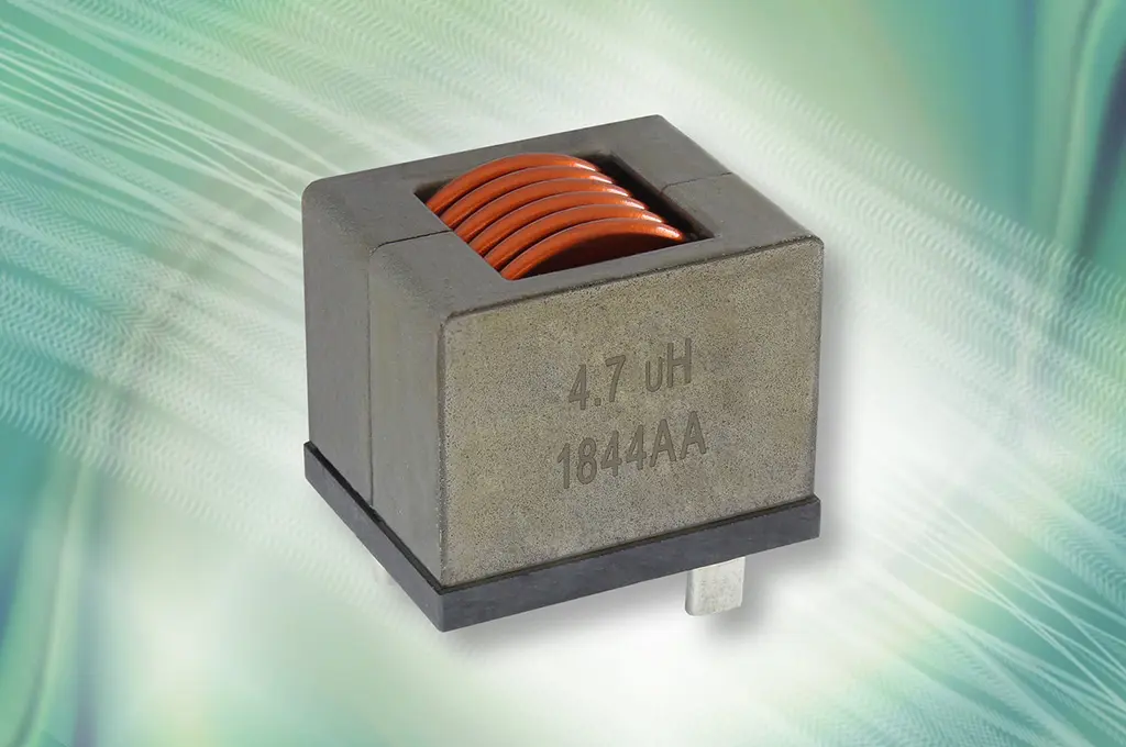
MALVERN, Pa.,Vishay Intertechnology, Inc. (NYSE: VSH) today introduced a new IHDM edge-wound, through-hole inductor with rated current up to 150 A for industrial and military applications. Featuring a powdered iron alloy core technology, the Vishay Custom Magnetics IHDM-1008BC-30 provides stable inductance and saturation over a demanding operating temperature range from -40 °C to +180 °C with low power losses and excellent heat dissipation.

RelatedPosts

EMC‑Compliant PCB and Connector Design Guidelines

Practical Value of Structural Diagnostics for Tantalum Capacitor Anodes

Hall-Effect Sensing for Harsh Environments: TT Electronics Selected in NASA’s Dragonfly Fan

The edge-wound coil of the device released today provides low DCR down to 0.25 mΩ, which minimizes losses and improves rated current performance for increased efficiency. Compared to competing ferrite-based solutions, the IHDM-1008BC-30 offers 30 % higher rated current and 30 % higher saturation current levels at +125 °C. The inductor’s soft saturation provides a predictable inductance decrease with increasing current, independent of temperature.

With an operating voltage up to 350 V, the device is ideal for DC/DC converters, inverters, motor and switching noise suppression, and high power switchmode power supplies in high current, high temperature applications, including industrial solar systems and charging stations for electric vehicles, as well as military defense systems.

The IHDM-1008BC-30’s standard terminals are stripped and tinned for through-hole mounting. Designed with ER2519 powered iron core, the dimensions are 25 mm x 20 mm x 23 mm. Vishay can customize the device’s mounting method, and performance, upon request. Options include bare copper, surface-mount, and press fit. To reduce the risk of whisker growth, the inductor features a hot-dipped tin plating. The device is RoHS-compliant, halogen-free, and Vishay Green.

Device Specification Table:

Dimensions (mm) 25 x 20 x 23
Inductance (µH) 1.2 to 10
DCR typ. (mΩ) 0.25 to 1.70
DCR max. (mΩ) 0.30 to 2.0
Heat rating current (A) 30 to 80
Saturation current (A) 30 to 110(1) / 45 to 150(2)
SRF typ. (MHz) 8 to 90

(1) DC current (A) that will cause L0 to drop approximately 20 %
(2) DC current (A) that will cause L0 to drop approximately 30 %

Samples and production quantities of the new inductor are available now, with lead times of 12 weeks.

Related

Recent Posts

Hall-Effect Sensing for Harsh Environments: TT Electronics Selected in NASA’s Dragonfly Fan

22.6.2026
16

Bourns Releases Automotive Gate Driver Transformer for Isolated Power

22.6.2026
8

Stackpole Releases High-Frequency Thin Film Chip Resistors for RF up to 50 GHz

19.6.2026
8

Knowles Expands High‑Q Ceramic Core Inductors for RF designs

19.6.2026
19

Vishay Unveils 1.5 kV IHDV High Voltage Power Inductors for EV and Industrial Converters

19.6.2026
25

SCHURTER Introduces PPTC Resettable Overcurrent Protection for Compact Electronics

18.6.2026
27

Samsung Introduces Automotive 1206 100uF X7T MLCC for Power Rails in ADAS and SoCs

17.6.2026
30

YMIN Hybrid Aluminum Capacitors for Automotive LiDAR Power Rails

17.6.2026
28

Samsung Presents Ultra‑Thin Silicon Capacitors for AI and Server PDN

17.6.2026
54

Upcoming Events

Jun 30
17:00 - 18:00 CEST

PSMA Capacitor Committee Webinar: High Voltage Pulse Capacitors

Jul 14
16:00 - 17:00 CEST

EMC Design Essentials: Mastering Varistors and Common Mode Chokes

Jul 21
16:00 - 17:00 CEST

Safety by design: X and Y Interference suppression capacitors for power line filters

View Calendar

Popular Posts

  • Boost Converter Design and Calculation

    0 shares
    Share 0 Tweet 0
  • Buck Converter Design and Calculation

    0 shares
    Share 0 Tweet 0
  • LLC Resonant Converter Design and Calculation

    0 shares
    Share 0 Tweet 0
  • Flyback Converter Design and Calculation

    0 shares
    Share 0 Tweet 0
  • MLCC and Ceramic Capacitors

    0 shares
    Share 0 Tweet 0
  • Earthing Systems and IEC Classification Explained

    0 shares
    Share 0 Tweet 0
  • Nvidia Vera Rubin: Why One AI Rack Needs So Many More MLCC Capacitors

    0 shares
    Share 0 Tweet 0
  • Dual Active Bridge (DAB) Topology

    0 shares
    Share 0 Tweet 0
  • SEPIC Converter Design and Calculation

    0 shares
    Share 0 Tweet 0
  • MLCC Case Sizes Standards Explained

    0 shares
    Share 0 Tweet 0

Newsletter Subscription


Passive Components Blog

© EPCI - Leading Passive Components Educational and Information Site

  • Home
  • Privacy Policy
  • EPCI Membership & Advertisement
  • About

No Result
View All Result
  • Home
  • Knowledge Blog
  • Dossiers
  • PCNS

© EPCI - Leading Passive Components Educational and Information Site

This website uses cookies. By continuing to use this website you are giving consent to cookies being used. Visit our Privacy and Cookie Policy.
Go to mobile version