

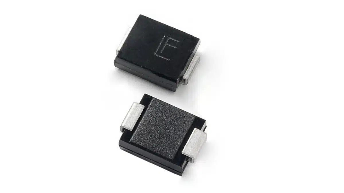
Littelfuse has introduced the TPSMD-FL Series, an automotive-grade family of surface-mount transient-voltage-suppression (TVS) diodes designed for 12 V vehicle electrical systems exposed to ISO 7637-2 Pulse 5b load-dump events.
The Littelfuse TVS diode series combines 3000 W peak pulse-power capability with the company’s FlatSuppressX technology, intended to hold transient clamping voltage low and comparatively stable during high-energy surges.
Key features and benefits
- FlatSuppressX low-clamping behaviour: The series uses a foldback I-V characteristic intended to create a flatter, more stable clamping-voltage profile than a conventional TVS diode during a severe transient.
- Potentially fewer protection stages: A lower clamping voltage can allow designers to protect downstream input capacitors, regulators and ICs without adding a secondary suppression stage, subject to validation at the required test level.
- High pulse-energy capability: Devices are rated for 3000 W peak pulse power dissipation.
- Automotive qualification: TPSMD-FL devices are AEC-Q101 qualified, supporting use in automotive electronic assemblies.
- Compact SMD implementation: The family uses the DO-214AB surface-mount package, providing high surge-handling capability in a board-mounted format.
- ESD robustness: Littelfuse specifies IEC 61000-4-2 protection up to 30 kV for both air and contact discharge.
For 12 V automotive modules, load dump is one of the more demanding supply-line surge conditions: disconnecting the battery while the alternator is charging can expose electronics to a high-energy overvoltage pulse. The key system benefit of a lower clamp is not simply TVS survival, but reducing the voltage stress transferred to components on the protected rail.
Technical highlights
| Parameter | TPSMD-FL Series |
|---|---|
| Product type | Automotive TVS diode |
| Technology | FlatSuppressX foldback I-V characteristic |
| Peak pulse-power capability | 3000 W |
| Automotive transient target | ISO 7637-2 Pulse 5b in 12 V systems |
| Automotive qualification | AEC-Q101 |
| ESD capability | IEC 61000-4-2: up to 30 kV air and contact discharge |
| Package | DO-214AB surface-mount package |
| Failure mode under excessive stress | Typically short circuit, according to the manufacturer |
The foldback characteristic is significant because the transient voltage across the protected rail is governed by the complete surge path, including the TVS response, wiring impedance, source impedance and current waveform. A TVS with a lower and flatter clamping response can create more usable voltage margin for downstream circuitry, particularly where the protected load includes automotive-grade DC/DC converters, low-voltage regulators or input-side ceramic capacitors.
Exact working-voltage, breakdown-voltage and clamping-voltage selections depend on the individual TPSMD-FL part number and should be verified in the current manufacturer datasheet.
Typical applications
Littelfuse identifies the TPSMD-FL Series for protection of I/O interfaces, VCC buses and other vulnerable circuits in automotive electronics. Likely design locations include the 12 V battery input or an internally distributed supply rail after the primary input connector.
- Zonal control modules and distributed vehicle controllers
- Body-control modules, including lighting, locking and comfort functions
- Powertrain and under-hood electronic assemblies
- Infotainment and cockpit electronics
- Vehicle gateways and networked ECUs
- Automotive DC/DC converter inputs and auxiliary power rails
- Externally accessible I/O and supply interfaces requiring ESD protection
The series is especially relevant where an ECU must handle high-energy load dump while board area and bill-of-material count are constrained. It may also suit zonal architectures, in which numerous distributed modules require local protection against disturbances on the 12 V network.
Design-in notes for engineers
- Select from the actual transient requirement. Confirm which ISO 7637-2 Pulse 5b severity level, source impedance and test configuration apply to the target vehicle platform; the appropriate TVS choice cannot be made from the 3000 W headline rating alone.
- Check clamp margin at the protected load. Compare the selected device’s specified clamping performance with the absolute maximum ratings of input capacitors, MOSFETs, regulators and ICs at the actual surge current.
- Use a short, low-inductance path. Place the TVS close to the protected connector or entry point, with a broad, direct return path to the relevant ground or supply-return plane. Excess trace inductance can add overshoot before the TVS clamps effectively.
- Coordinate with input filtering. The TVS should be assessed alongside reverse-battery protection, fusing, EMI filtering, common-mode chokes and input capacitors. These elements influence both surge current sharing and conducted-emissions performance.
- Assess normal operating voltage and cold-crank behaviour. Ensure the reverse standoff voltage accommodates expected battery and charging-system conditions without excessive leakage, while the protected circuit still functions through low-voltage operating events.
- Consider the specified failure mode. Littelfuse states that an over-specified voltage or current event typically causes a short circuit. The upstream fuse, current-limiting element and diagnostic strategy should therefore be designed to manage a shorted protection device safely.
- Validate at module level. Bench characterization is useful, but final performance should be confirmed with the production PCB layout, cable harness, input filter and representative load using the required automotive transient test plan.
Source
This article is based on Littelfuse’s August 2026 product announcement and the official TPSMD-FL Series product information. Electrical ratings and application suitability should be confirmed against the latest manufacturer datasheet before releasing a design to production.