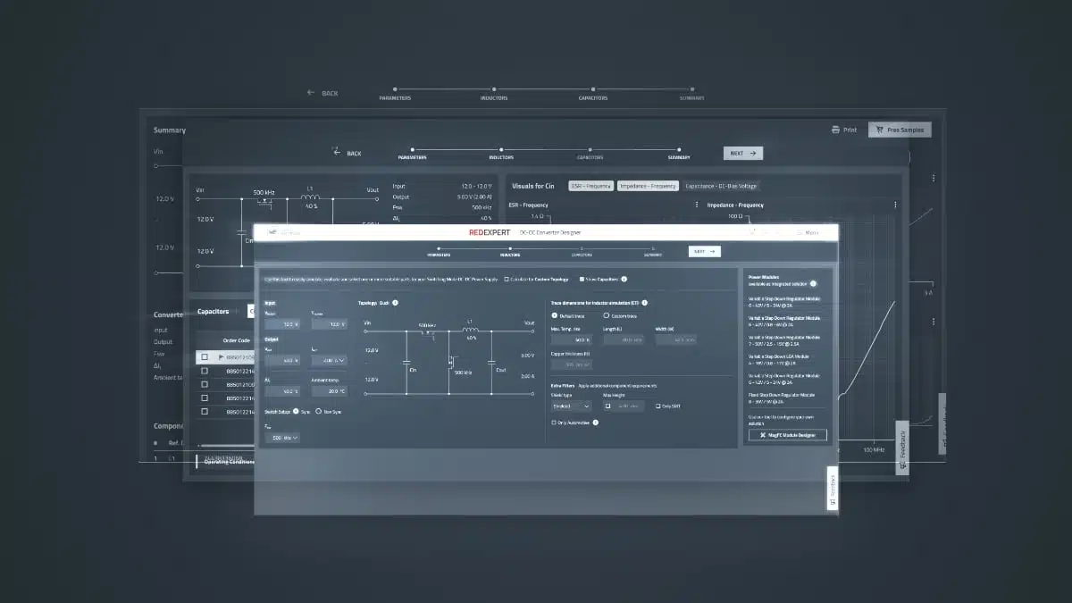
Würth Elektronik has released a completely revised version of its REDEXPERT DC‑DC Converter Designer, an online tool that turns basic application parameters into a realistic, design‑ready bill of materials.
The Würth Elektronik‘s REDEXPERT DC‑DC Converter Designer update focuses on accurate inductor and capacitor behavior under real operating conditions, giving power electronics engineers and buyers a more reliable starting point for converter design and component selection.
Key features and benefits
- Accurate inductor loss and DC‑bias modeling
The core of the new DC‑DC Converter Designer is a proprietary loss calculation method based on extensive inductor characterization under realistic conditions. This means losses and temperature rise are derived from measured behavior instead of idealized models or sparse datasheet values. The tool explicitly considers inductance change with DC bias, which is critical for avoiding saturation and performance degradation in compact power stages. - Realistic ceramic capacitor behavior under voltage
The tool models the drop in capacitance of MLCCs under operating voltage, a common source of over‑optimistic design margins if engineers only rely on nominal datasheet values. Designers can therefore size input and output capacitors based on effective capacitance in‑circuit rather than nameplate values, improving stability, ripple performance, and lifetime. - Worst‑case oriented design support
A new worst‑case option for losses and temperature rise allows engineers to evaluate designs against the upper limits of expected stress. This is particularly helpful for automotive, industrial, and other mission‑critical applications where ambient temperature, airflow, and load conditions can vary widely and must be tolerated with margin. - From input parameters to complete BOM
The overview page consolidates all simulation results and generates a bill of materials with up to six components, including magnetics, capacitors, and a suitable controller IC. Engineers can directly request free samples or add the proposed components to the shopping cart, streamlining the path from design concept to prototype.
Typical applications
The DC‑DC Converter Designer targets a wide range of non‑isolated DC‑DC converters in power electronics, from simple point‑of‑load regulators to more demanding converter stages.
Typical use cases include:
- Point‑of‑load buck converters on digital boards (MCUs, FPGAs, SoCs) where accurate inductor and capacitor behavior is essential for low ripple and good transient response.
- Boost and SEPIC converter stages for sensor front‑ends, automotive subsystems, and auxiliary rails that must stay stable over wide input voltage swings.
- Power supplies in industrial controllers, communication equipment, and embedded systems where thermal margins and component derating must be validated early.
- Designs that must meet automotive requirements, where height constraints, shielding, and elevated ambient temperatures drive careful component selection.
By integrating topology selection and realistic component behavior into one workflow, the tool is suited both for quick feasibility checks and for more in‑depth optimization of existing designs.
Technical highlights
Supported topologies and operating modes
The revised DC‑DC Converter Designer automatically proposes a suitable topology based on the user’s input conditions, while still allowing expert users to override this behavior.
- Supported automatic topologies:
- Buck converter (synchronous and asynchronous)
- Boost converter (synchronous and asynchronous)
- SEPIC converter
- User‑defined topology mode for specialized or less common converter arrangements, giving experienced engineers freedom to explore non‑standard architectures while still benefiting from the component models.
This combination allows engineers to start from a high‑level requirement (input/output voltage, current, ripple, etc.) and let the tool suggest an implementation, or alternatively to validate a topology they have already chosen.
Inductor and capacitor modeling
The tool’s main distinguishing feature is its focus on realistic passive component behavior:
- Inductors are modeled using loss data derived from Würth Elektronik’s own characterization of its portfolio. This includes core and copper losses over frequency, current, and temperature, providing more accurate estimates of efficiency and hot spot temperatures in the application.
- DC‑bias effects on inductance are directly included. Instead of assuming a constant inductance, the tool reflects how the effective inductance drops as current increases, which can affect ripple, control loop stability, and saturation margin.
- Ceramic capacitors are modeled with their voltage‑dependent capacitance. Rather than assuming nominal capacitance, the tool accounts for the reduction under bias, which is especially relevant in compact, high‑voltage or high‑temperature designs.
The result is that predicted losses, temperatures, and effective capacitances are much closer to what engineers later measure on the actual PCB, reducing the number of prototype iterations needed to converge to a robust solution.
Analytical and comparison capabilities
Beyond single‑component sizing, the DC‑DC Converter Designer now supports richer analysis and comparison:
- The system recommends the five most suitable inductors based on a weighted evaluation of performance and package size, helping designers balance efficiency and footprint.
- Multiple candidate components can be displayed in a single graph, showing losses as a function of output current and switching frequency. This makes trade‑offs between ripple, efficiency, and temperature more transparent.
- Enhanced graph features include zooming, a crosshair cursor for reading off exact values, and export options to image or Excel formats for documentation, design reviews, or internal reports.
- Experienced users can bypass the automatic recommendations and manually load any Würth Elektronik component into the tool, giving direct access to the broader inductor and capacitor portfolio for fine‑tuning.
These analytical functions make the tool usable not only at the concept stage, but also later when performing design optimization or comparing alternative component strategies.
Integration with other Würth Elektronik tools
To bridge discrete designs with module‑based solutions, the DC‑DC Converter Designer links directly to the MagI³C Power Module Designer. This allows users to:
- Compare a traditional discrete design (inductor plus controller IC plus passives) with a fully integrated power module solution for the same application parameters.
- Evaluate trade‑offs between design flexibility, PCB area, thermal behavior, and design‑in complexity.
The tool also recommends a suitable microcontroller or controller IC for the specified input parameters, further shortening the path from system‑level requirements to a near‑final schematic.
Availability and workflow
DC‑DC Converter Designer access
The DC‑DC Converter Designer is available as an online service within the REDEXPERT platform. Once logged in, users can:
- Enter basic application data such as input voltage range, output voltage, output current, and performance targets.
- Let the tool select topology, passive components, and controller IC according to the defined constraints.
- Review the generated bill of materials and simulation results, including thermal and loss estimates.
From the generated BOM, components can be requested as free samples or ordered directly, allowing hardware teams to move quickly from design to prototyping.
Output and documentation
The tool’s overview page consolidates the main design results:
- Selected topology and key design parameters.
- Recommended inductor(s), capacitors, and controller IC, with associated electrical data.
- Loss and temperature estimates for the major power components.
- A complete bill of materials with up to six components, ready for documentation or integration into internal part databases.
Engineers can export graphs and data for design documentation, internal reviews, or compliance reporting, ensuring that decisions regarding magnetics and passive components are traceable and backed by realistic simulations.
Design‑in notes for engineers
When using the revised DC‑DC Converter Designer in real projects, a few practical considerations can help engineers and purchasers get the most out of the tool:
- Treat DC‑bias and voltage dependency as mandatory inputs, not details
For compact, high‑performance designs, the change in inductance under DC‑bias and the drop in MLCC capacitance under voltage can drastically affect ripple and stability. Designs that look fine with nominal values may run too hot or fail to meet dynamic requirements if these dependencies are ignored. - Use the worst‑case mode early in the design
Running the design through the worst‑case loss and temperature option early in the project helps identify parts that might be marginal at elevated ambient temperatures or at the edges of the input/output range. This is particularly important for automotive and industrial markets where derating policies must be followed. - Leverage automatic topology selection as a sanity check
Even if the topology is pre‑selected at system level, letting the tool propose its own topology can serve as a cross‑check against the initial concept. Differences between the automatic choice and the original plan may highlight opportunities for better efficiency or lower component count. - Use component comparison plots to justify purchasing decisions
The loss versus output current and frequency plots can be used to compare larger versus smaller footprints, or shielded versus unshielded components. This supports discussions with purchasing departments when higher‑performance components are selected for thermal or EMC reasons. - Cross‑check with the MagI³C Power Module Designer
For applications where time‑to‑market or design resources are constrained, using the link to the MagI³C Power Module Designer makes it straightforward to compare a fully integrated module solution with the discrete design. In many cases, the module may reduce design risk and simplify layout, even if the unit price is higher. - Always confirm final ratings against the datasheet
While the tool provides realistic estimations, final design decisions for safety‑relevant parameters, derating, and worst‑case operation should be confirmed against the latest manufacturer datasheets and application notes. Where exact ratings are critical, designers should refer directly to the datasheet values provided by Würth Elektronik.
Source
The information in this article is based on an official press release and related material published by Würth Elektronik about the updated REDEXPERT DC‑DC Converter Designer, interpreted and commented from the perspective of an independent technical editorial site.