











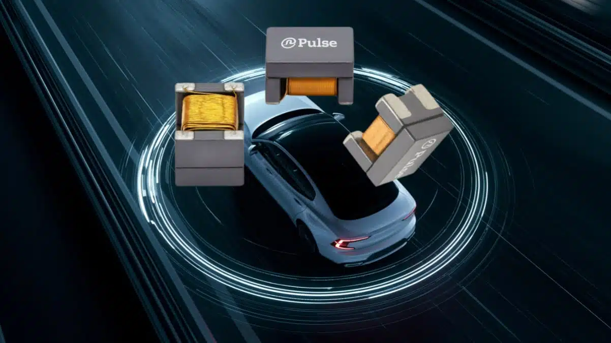
YAGEO Group has expanded its AC1210 series of signal common-mode chokes for CAN and CAN-FD networks.
The YAGEO 1210-size SMD common-mode chokes combine common-mode noise suppression with a compact 3.2 mm × 2.5 mm footprint, targeting automotive and industrial communication nodes exposed to harsh electromagnetic environments.
As CAN-FD data networks spread across vehicle architectures, EMC countermeasures must reduce cable-borne and radiated noise without creating excessive differential-mode attenuation or signal distortion. The AC1210 family provides several inductance and impedance options so designers can match the choke to the bus, ECU location and EMC target.
Key features and benefits
- Compact 1210 package with a 3.2 mm × 2.5 mm footprint, useful where gateway modules, camera units and body-control electronics have limited board area.
- Inductance options of 11 µH, 22 µH, 51 µH and 100 µH.
- CAN Class I, II and III support, with stated compatibility for CAN and CAN-FD applications.
- Operating-temperature options extending to -55°C to +150°C, depending on the selected model.
- AEC-Q200 qualification for automotive-grade component reliability.
- Low DC resistance options to limit voltage drop and heating in the bus path.
- Optional side plating on selected variants, intended to strengthen solder-joint robustness under vibration and thermal cycling.
- Compliance support for IEC 62228-3 and CiA 110 test requirements, with third-party measurement data stated to be available.
- RoHS-compliant construction.
A common-mode choke is inserted in series with both bus conductors. Ideally, wanted differential CAN data passes with little disturbance, while noise that appears in common mode on both lines encounters a substantially higher impedance.
Technical highlights
| Parameter | AC1210 series information |
|---|---|
| Component type | Signal common-mode choke |
| Intended interfaces | CAN and CAN-FD; manufacturer also identifies related automotive communication-system use cases |
| Package size | 1210, 3.2 mm × 2.5 mm |
| Inductance choices | 11 µH, 22 µH, 51 µH, 100 µH |
| Maximum operating temperature | Up to +150°C, depending on model |
| Standards referenced | IEC 62228-3 and CiA 110 |
| Qualification | AEC-Q200 |
| Insulation classification | Functional insulation |
| Isolation voltage | 125 VDC, according to the available product listings |
The lower-inductance 11 µH and 22 µH versions are specified with a -50°C to +150°C operating range. The 51 µH and 100 µH options listed on the manufacturer product page have a -40°C to +125°C range, so temperature capability should be checked at individual part-number level rather than assumed across the entire family.
| Part number | Inductance | Impedance at 10 MHz | Rated current | DC resistance | Operating temperature |
|---|---|---|---|---|---|
| AC1210-110-C | 11 µH | 560 Ω | 300 mA | 500 mΩ | -50°C to +150°C |
| AC1210-220-C | 22 µH | 1.2 kΩ | 300 mA | 800 mΩ | -50°C to +150°C |
| AC1210-510-C | 51 µH | 2.8 kΩ | 150 mA | 1 Ω | -40°C to +125°C |
| AC1210-101-C | 100 µH | 4.2 kΩ | 100 mA | 3 Ω | -40°C to +125°C |
| AC1210-101-D | 100 µH | 4.7 kΩ | 100 mA | 3 Ω | -40°C to +125°C |
The impedance values above are quoted at 10 MHz and are useful for comparing common-mode suppression options, but they are not a complete predictor of performance across an OEM EMC test band. Selection should therefore include the manufacturer datasheet and, where available, measured S-parameter or common-mode attenuation data.
Typical applications
The AC1210 series is aimed at CAN and CAN-FD interconnects in electrically demanding systems, including:
- Battery-management systems in electric and hybrid vehicles
- Powertrain, body-control and automotive gateway modules
- Advanced driver-assistance systems, including camera, radar and LiDAR modules
- Infotainment, navigation and V2X communication hardware
- Lighting, airbag and safety/security controllers
- Tire-pressure-monitoring and sensor networks
- Industrial CAN communication networks and distributed control systems
For automotive platforms, a common 1210 footprint across several inductance values can simplify PCB reuse. A hardware team can retain the same land pattern while tuning the choke value during EMC validation or while adapting a controller to different node positions and harness conditions.
Design-in notes for engineers
- Place the choke at the interface. Locate it close to the CAN transceiver or connector according to the system EMC strategy; the optimum position depends on whether the dominant concern is immunity at the ECU or cable emissions.
- Preserve pair symmetry. Route CAN_H and CAN_L as a tightly coupled, length-matched pair through and around the choke. Asymmetrical routing can convert differential signal energy into common-mode noise.
- Assess the full bus network. A choke affects the electrical behaviour of the complete node, including transceiver, TVS protection, common-mode capacitors, split termination and harness. Validate the final combination rather than assessing the choke alone.
- Do not select by inductance alone. Compare common-mode impedance over the relevant frequency range, DC resistance, current rating and the intended CAN class. Higher inductance can improve low-frequency common-mode impedance, but may not be the best choice for every data-rate or EMC issue.
- Check differential-mode behaviour. CAN and CAN-FD signal margins depend on low differential insertion loss and controlled impedance. Use the manufacturer’s detailed data and system-level testing to verify that arbitration and high-speed data phases remain robust.
- Verify environmental margins. For under-hood, traction-battery or high-temperature sensing electronics, choose the -50°C to +150°C versions where the application requires that range.
- Review mechanical reliability. Where board flex, vibration or thermal cycling are severe, side-plated variants may be worth considering, subject to the applicable part-number documentation and assembly qualification.
- Include protection coordination. A common-mode choke is an EMC component, not a substitute for transient protection. Coordinate it with suitable CAN-line TVS protection and the relevant ISO/OEM transient requirements.
Source
This article is based on YAGEO Group’s product announcement for the AC1210 CAN and CAN-FD common-mode choke series and the manufacturer’s current online product catalogue. Electrical parameters and availability should be verified against the latest individual datasheet before release to production.












