Humanoid robots are rapidly becoming one of the most demanding integration targets for internal data and power interconnects. Compared with conventional industrial robots, they combine more sensors, more degrees of freedom, compact joint packaging, distributed compute, and an unusually strong need for lightweight, mechanically compliant internal cabling.
Single Pair Ethernet (SPE) is therefore emerging as a potential building block for in-robot networks. It can reduce cabling bulk while bringing Ethernet-based communication closer to sensors, joint controllers, zonal electronics, and compute nodes. Its suitability nevertheless depends on the selected Ethernet physical layer, topology, power architecture, timing requirements, EMC environment, and mechanical qualification—not simply on replacing an existing cable with one twisted pair.
This article draws on Murata’s current humanoid-robotics resources and on the Single Pair Ethernet System Alliance (SPESA) white paper on humanoid in-robot networks. Murata positions connectivity within a broader humanoid electronics platform spanning sensing, power, motion control, and system reliability. Murata Robotics Component Solutions and Murata Humanoid Robotics provide the primary industry context, while the SPESA white paper provides the SPE-oriented architecture discussion.
Add this directly after the introduction, ideally after the Murata/SPESA source paragraph and before “Why humanoids need a different network approach.” It accurately reflects the article’s scope: SPE can reduce harness burden and support Ethernet convergence, but its success depends on PHY selection, PoDL limits, timing, EMC, and mechanical validation.[passive-components]
Key takeaways
- Humanoid robots need lighter, more distributed internal networks because they combine dense sensing, numerous actuators, compact moving joints, AI compute, and demanding cable-routing constraints.
- Single Pair Ethernet (SPE) can reduce harness bulk and support Ethernet-based integration for sensors, joint controllers, zonal electronics, diagnostics, and selected compute links.
- Choose the SPE PHY by endpoint and topology: 10BASE-T1S suits lower-rate multidrop sensing, while 100BASE-T1 and 1000BASE-T1 fit switched point-to-point links with higher throughput needs.
- PoDL is best suited to low-power sensors and compact controller nodes; high-current motors, brakes, and joint actuators still require dedicated power conductors.
- Deterministic performance is a system-level design task. TSN-capable endpoints and switches, time synchronization, traffic scheduling, software support, and validated latency/jitter budgets matter—not the SPE cable alone.
- Passive components and EMC design are critical to robustness. PoDL inductors, common-mode chokes, MLCC decoupling, protection devices, PCB return paths, connector transitions, shielding, and high-flex cables must be designed as one channel.
- A hybrid, zonal architecture is often the practical route. Use SPE where it improves weight, routing, serviceability, diagnostics, and scalability, while retaining specialized links or independent safety paths where power, bandwidth, or fault containment require them.
Why humanoids need a different network approach
Humanoid robots are not simply industrial robot arms with more axes. They are mobile, sensor-rich electromechanical systems designed to operate in environments built for humans, often with AI-based high-level control, voice or language interaction, dexterous manipulation, and direct collaboration with people.
| Design aspect | Industrial robot arm | Humanoid robot |
|---|---|---|
| Axes / degrees of freedom | Some: 6 plus gripper or tool | Massive: total up to 72+; 28 DoF plus two dexterous hands, with approximately 11 to 22 DoF per hand |
| High-level control | Programmable Logic Controller with a kinematics motion model and PLC-in-the-loop control | AI robotic computer with a humanoid robot foundation model using System 1 and System 2; stable locomotion, voice interaction and dexterous manipulation |
| Low-level control protocols | PROFINET, EtherCAT, EtherNet/IP, POWERLINK, Sercos III and CC-Link | CAN/CAN FD, EtherCAT, PROFINET, EtherNet/IP and TSN |
| Sensors | Limited set: joint positions and robot-state encoders | Extensive set: joint position and state encoders, force/torque sensing, 3D environment sensing through cameras, radar, lidar and ultrasonic sensors, tactile/touch sensors, IMUs, microphones and other sensors |
| Robot-human interaction | Often segregated from people by guarding or safety zones; collaborative variants are also used | Direct collaboration with humans and other robots or machines |
| Flexibility / target application | Low; defined and programmed single task, equipped manipulator, fixed application | High; reinforcement learning, Sim2Real, multi-purpose operation and tool use; adaptable applications |
| Costs | High | High but decreasing rapidly |
| Functional safety | Established industrial and collaborative-robot safety practices | Emerging humanoid-specific practices; likely to combine collaborative-robot safety concepts with application-specific risk assessment |
As the original comparison shows, humanoids can scale to roughly 72 or more total degrees of freedom in advanced configurations, combine many more sensing modalities than conventional robot arms, and rely increasingly on AI-centric high-level control rather than only PLC-style logic. This has an immediate effect on internal networking: the robot must support a larger volume of heterogeneous traffic while still preserving predictable timing for local motion control loops.
Key features and benefits
- Single Pair Ethernet reduces cable bulk by using a single twisted pair rather than larger multi-pair or multicore communication cabling.
- Lower cable mass and smaller bend radius can ease routing through arms, wrists, torso sections, neck structures, and other mechanically constrained robot zones.
- Reduced cable stiffness can help lower mechanical resistance in dynamic joints and support longer service life under repeated flexing.
- SPE aligns well with Ethernet-based architectures, making it relevant for future software-defined robot platforms.
- Ethernet with TSN-capable endpoints and switches can support synchronized, more deterministic communication where the selected PHY, switch hardware, software stack, and time-synchronization design meet the application latency and jitter budget.
- PoDL can simplify connectivity for low-power sensors and smaller control nodes, reducing harness count and connector complexity.
- Diagnostic functions such as signal quality assessment can improve maintenance and support validation of cable and connector integrity.
Technical challenges in humanoid robots
Mechanical and actuator density
Humanoids must balance low mass with high mechanical output. The payload ambitions may be above 25 kg, joint torque up to 300 Nm, and the use of lightweight structural materials such as magnesium alloys and carbon composites. These choices reduce inertial load, but they also make cable routing and dynamic mechanical compliance more important because the harness cannot become a hidden source of stiffness or fatigue.
The humanoid typically integrates about 50 to 80 actuators. When actuator count rises to that level, the communication network must distribute control and feedback signals through many compact, moving subsystems without excessive cable volume or timing uncertainty.
Thermal and energy constraints
Thermal management is a major challenge in dense mechatronic systems, where compact joint modules, high-torque actuators, and AI compute boards generate significant heat. This relates also to decisions about battery technology, hot-swappable packs, charging strategy, and battery management as central enablers of operational flexibility.
These constraints matter for the communication architecture because harness mass, connector density, and placement of power and data links influence both internal packaging and thermal design. A lighter, smaller communication layer helps free mechanical and thermal margin elsewhere in the robot.
Large sensor count and mixed traffic
Humanoid robots incorporate a large number of sensors, including encoders, force and torque sensors, cameras, distance sensors, tactile arrays, IMUs, and microphones. The challenge is to fuse these heterogeneous signals in real time, often at high aggregate data rates.
For networking, this means a humanoid does not carry just one type of traffic. It carries multiple traffic classes with different requirements for bandwidth, latency, synchronization, and fault tolerance.
Data classes in a humanoid in-robot network
| Data or control class | Typical source | Main requirement | Why SPE is relevant |
|---|---|---|---|
| Vision and perception | Cameras, lidar, radar | High bandwidth, scalable aggregation | Supports compact Ethernet-based transport for dense sensing zones |
| Robot-state feedback | Encoders, IMUs, tactile and force sensors | Predictable timing and synchronization | Fits deterministic architectures where TSN-style behavior matters |
| Motor-control traffic | Joint command and feedback loops | Very low latency, bounded jitter | Encourages use of real-time capable Ethernet infrastructure |
| Audio and language-related data | Microphones, command interfaces | Moderate bandwidth, system integration | Can coexist on a unified backbone with other non-power traffic |
| Diagnostics and maintenance | Health monitoring, link checks, configuration | Reliable access and troubleshooting visibility | SPE ecosystem includes diagnostic quality concepts such as SQI measurement |
Selecting the SPE physical layer
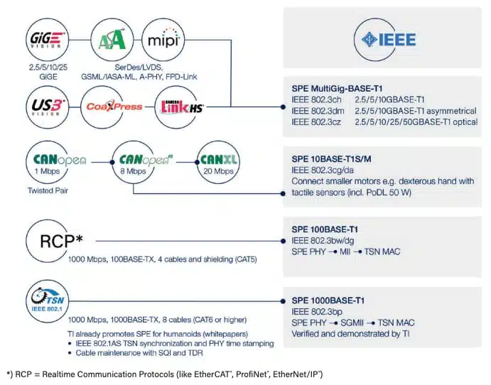
Single Pair Ethernet is attractive where a humanoid needs reduced harness mass, compact routing, Ethernet-based integration, and scalable connectivity for distributed low-power endpoints. SPE is not a single data-rate technology. A humanoid robot may use different SPE physical layers in different zones: a low-speed multidrop branch for distributed sensors, switched point-to-point links for joint or zonal controllers, and higher-rate links for locally aggregated perception traffic. The network architecture should therefore start with traffic and endpoint requirements rather than a blanket decision to use SPE everywhere.
The most useful distinction is between multidrop sensor networking and switched Ethernet. 10BASE-T1S is intended for lower-speed multidrop segments and can use Physical Layer Collision Avoidance (PLCA) to make shared-medium access more predictable. By contrast, 100BASE-T1 and 1000BASE-T1 are principally point-to-point PHYs suited to switched links and higher-throughput endpoints. SPE implementations span approximately 10 Mb/s to 1 Gb/s in widely deployed industrial and automotive-oriented variants; designers should verify exact reach, cabling, connector, electromagnetic, and PHY requirements against the selected standard and supplier documentation.
A practical humanoid network will often be hybrid. It may retain CAN or CAN FD, EtherCAT, dedicated safety wiring, specialized camera interfaces, and separate high-voltage motor-power wiring where these choices provide a better fit than a universal Ethernet conversion. The objective is not protocol uniformity at any cost; it is a lighter, diagnosable, scalable, and verifiably safe architecture.
| SPE option | Typical humanoid role | Topology | Main advantage | Important limitation |
|---|---|---|---|---|
| 10BASE-T1S | Distributed low-rate sensors, diagnostics, simple actuator peripherals | Multidrop bus | Reduces wiring for many low-bandwidth nodes; PLCA can improve access predictability | Not appropriate for raw camera, lidar, or high-rate perception data |
| 100BASE-T1 | Point-to-point joint controller, zonal controller, sensor aggregation link | Switched point-to-point | Useful balance of bandwidth, cable simplicity, and endpoint density | Requires a properly designed switched architecture rather than a shared multidrop branch |
| 1000BASE-T1 | Local perception aggregation, compute-zone interconnect, high-rate sensor uplink | Switched point-to-point | Supports substantially higher throughput in a compact single-pair channel | Link budget, EMC, connector choice, and PCB/channel design become more demanding |
| Separate high-bandwidth architecture where required | Multi-camera aggregation, high-resolution perception, compute backplane | Architecture-specific | Prevents a single link choice from becoming a system bottleneck | SPE is not automatically the optimum answer for every high-data-rate subsystem |
Core technical advantages
- Slimmer and lighter cables than traditional Ethernet or multicore alternatives.
- Smaller bending radius, which is valuable in elbows, wrists, necks and other compact moving zones.
- Lower mechanical stress during bending, helping support longer cable lifetime.
- Higher packing density in robots with many distributed endpoints.
- Communication options ranging from low-speed sensing links to 1 Gb/s implementations, depending on the selected SPE PHY, topology, and channel design.
- Compatibility with deterministic Ethernet concepts such as TSN.
- Optional PoDL capability for suitable low-power nodes.
In a humanoid, every gram of harness mass, every millimeter of cable diameter, and every limitation in bend behavior can affect assembly, reliability, and motion performance.
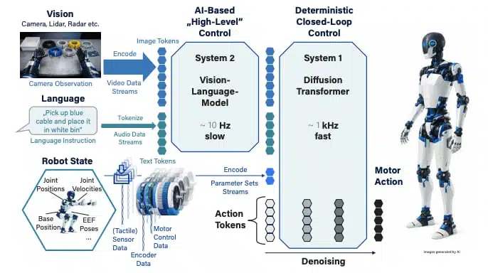
GR00T N1 as an example of mixed robot data flows
NVIDIA introduced GR00T N1 as an open humanoid-robot foundation model that combines visual perception, language input, and action generation. In the context of in-robot networking, it illustrates why humanoid platforms can contain data streams with very different bandwidth and timing characteristics—from high-volume perception data to rapid local motion-control feedback.
Dual-System Architecture
Inspired by cognitive principles, GR00T N1 employs two tightly coupled systems:
- System 2 – Vision-Language Module
A powerful Vision-Language Model (VLM) that processes image data and natural language commands to generate contextual tokens. This module acts as the “deliberative mind,” responsible for reasoning and planning. - System 1 – Diffusion Transformer
A high-frequency action generator that uses VLM outputs and the robot’s state to produce smooth, real-time motor actions.
This represents the “intuitive mind,” focused on execution.
Both modules are Transformer-based and trained end-to-end on a diverse dataset of real robot trajectories, human demonstrations, and synthetic scenarios. This synergy enables seamless coordination between high-level reasoning and low-level control – bringing humanoid robots closer to human-like adaptability and precision.
Technology transfer from automotive E/E architecture
Humanoid robots face internal interconnect constraints that increasingly resemble those of modern vehicles: a growing number of distributed sensors and electronic control units, limited routing space, strict mass targets, electrical noise from high-power switching loads, and pressure to reduce wiring complexity. Automotive engineering has addressed comparable challenges through Ethernet-based networks, distributed electronics, and a shift from domain-centric to zonal E/E architectures.
In a conventional domain architecture, electronic control units are grouped by function—for example, powertrain, body, chassis, or infotainment—and can require long individual harness runs across the system. A zonal architecture instead groups electronics by physical location. Local zonal controllers collect nearby sensor and actuator connections, while a higher-bandwidth backbone connects the zones to central compute and power-management functions.
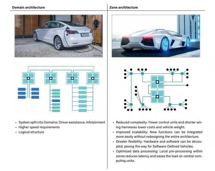
For humanoid robots, equivalent zones may include the head, torso, battery region, left and right arms, hands, legs, and feet. Local aggregation can shorten cable routes, improve serviceability, limit the number of long harness runs, and allow each region to be designed around its own mix of sensing, actuation, power conversion, and communication requirements.
The analogy should not be overstated. Humanoids have much more continuous articulation, tighter bend radii, smaller available cable volume, and different failure modes than passenger vehicles. Nevertheless, automotive zonal architecture provides a useful design reference for distributed controller placement, Ethernet backbone design, power distribution, diagnostics, and harness reduction. Murata notes that automotive electronics are moving toward zonal architectures in which IMUs are mounted directly on ECUs to reduce wiring and simplify system architecture through integration.
Migrating toward SPE
Figure 3 provides a practical migration path for moving from today’s mixed protocol landscape toward a more unified SPE-based architecture.
Practical migration path
A staged migration rather than a complete overnight replacement of every existing link is recommended. The process begins with mapping current protocols and bottlenecks, then defining functional zones, selecting SPE insertion points, upgrading hardware where needed, aligning protocols to deterministic Ethernet approaches, and validating performance under dynamic real-world load.
| Migration step | Main objective | Design questions |
|---|---|---|
| Assess current architecture | Identify current buses, latency bottlenecks and cable complexity | Which links are bandwidth-limited, heavy, difficult to route or hard to scale? |
| Define functional zones | Group links by vision, locomotion, haptics, manipulation and compute | Which zones benefit most from local aggregation and lighter wiring? |
| Select SPE insertion points | Apply SPE where it gives the clearest mechanical or networking gain | Are the endpoints low power, bandwidth-sensitive or routing-constrained? |
| Upgrade hardware | Introduce compatible connectors, PHYs and switches | Is the chosen ecosystem ready for the needed protocol and environmental demands? |
| Align protocols | Move toward deterministic Ethernet where required | Does the software stack support the needed timing and synchronization model? |
| Test and validate | Confirm performance under realistic operating stress | Does the network maintain deterministic behavior during simultaneous motion and sensing load? |
Cabling and connector requirements
For engineers working with passives, shielding and interconnect support circuitry are just as important as the cable itself. Controlled impedance, common-mode behavior, power injection, filtering, and connector termination quality all influence whether a compact in-robot Ethernet link works reliably under motion and electrical stress.
Power delivery and PoDL
Power over Data Line (PoDL) can combine data and DC power on a suitable SPE link, making it attractive for low-power sensors, compact controller nodes, and selected peripheral modules. It can reduce harness count and simplify installation where the endpoint power demand, cable resistance, connector rating, thermal environment, and power-source equipment are all compatible with the chosen PoDL class.
PoDL should not be treated as a substitute for high-power actuator supply wiring. Humanoid joints, motors, brakes, and high-current power converters typically require dedicated power conductors designed around current capability, voltage drop, thermal margin, fault protection, and conducted-EMI containment. Industry overviews commonly cite PoDL implementations of up to approximately 52 W at the power sourcing equipment for higher classes, but usable power at a robot endpoint depends on the complete power channel and should never be inferred from a headline value alone.
Power-path selection guidance
| Device or subsystem | Preferred power approach | Design rationale |
|---|---|---|
| Low-power sensors and small controller nodes | PoDL can be evaluated | A shared data-and-power link can reduce connector count, harness mass, and local wiring complexity |
| Distributed diagnostic, status, and low-power I/O nodes | PoDL is often a practical candidate | These endpoints commonly benefit from simplified installation and relatively modest power demand |
| High-power joint actuators and motor drives | Dedicated power conductors | Motor current, switching noise, transient load demand, and functional safety require a separately engineered power path |
| Mixed sensor-plus-actuator modules | Hybrid architecture | SPE can carry control, feedback, and diagnostics while dedicated conductors deliver motor or brake power |
Inductor tolerance is an important EMC and signal-integrity parameter in PoDL coupling circuits. Differences in inductance can disturb common-mode symmetry and promote common-mode-to-differential-mode conversion, which may reduce emissions or immunity headroom. For dynamically operating humanoid robots, coupling inductors should be chosen based on tolerance, DCR, current rating, saturation headroom, temperature range, parasitic effects, and high-frequency common-mode performance—not solely on their nominal inductance.
Real-time networking and synchronization
Humanoid robots need more than high throughput. They need bounded latency, controlled jitter, time synchronization, fault detection, and predictable behavior when many sensing and actuation functions operate simultaneously. The appropriate architecture depends on how the control system partitions local and central loops: a local motor controller may close a fast current or torque loop independently, while the network transports setpoints, feedback, synchronization information, diagnostics, and coordinated motion commands.
EtherCAT, CAN/CAN FD, PROFINET, EtherNet/IP, and Ethernet with Time-Sensitive Networking (TSN) capabilities can all appear in robot architectures, but they are not interchangeable. Their usefulness depends on the control software, PHY and switch hardware, synchronization mechanism, endpoint support, and fault-response design. TSN should therefore be specified by the required functions rather than as a generic feature label.
For an Ethernet-based deterministic domain, engineers should evaluate time synchronization, scheduled or prioritized traffic, traffic shaping, queue management, and redundancy against the actual end-to-end latency and jitter budget. Common standards associated with these functions include IEEE 802.1AS for time synchronization and IEEE 802.1Qbv for time-aware scheduling. A fast robot-wide control-loop rate should not be assumed as a universal requirement: update rates are application-specific and should be derived from actuator dynamics, local control partitioning, sensor sampling, safety response requirements, and permitted timing error.
Passive-component and EMC design
SPE in a humanoid is not only a cable and PHY decision. Link margin depends on the complete channel: the PHY, PCB launch, AC-coupling or PoDL network where applicable, circuit protection devices, common-mode components, connector, cable, shielding method, termination, and surrounding electromechanical environment. A link that passes a static bench test may still fail emissions, immunity, packet-error, or synchronization requirements when routed beside switching motor drives and repeatedly flexed in an articulated joint.
PoDL magnetics
PoDL coupling inductors require more than a correct nominal inductance. Evaluate inductance tolerance, DCR, saturation current, temperature rise, DC-bias behavior, winding symmetry, self-resonance, parasitic capacitance, and common-mode response. Tight tolerance is particularly important where imbalance can convert common-mode interference into differential noise that affects the SPE channel.
Common-mode suppression
Common-mode chokes can help attenuate noise that couples onto a cable pair from motor inverters, DC/DC converters, battery-management electronics, and other switching sources. They must be selected with attention to common-mode attenuation, differential-mode insertion loss, impedance versus frequency, current capability, parasitic capacitance, and the PHY/channel return-loss budget. An unsuitable choke or poor placement can degrade the very signal integrity it is intended to protect.
Protection and decoupling
ESD and surge-protection devices should have capacitance, leakage, clamping behavior, and dynamic resistance compatible with the selected PHY and channel design. At every endpoint, MLCC selection must account for DC-bias capacitance loss, temperature characteristics, voltage derating, ripple-current environment, mechanical stress, and anti-resonance with bulk capacitance or cable inductance. The relevant design target is stable local power impedance over the frequency range of the endpoint load transient, not merely a large nominal capacitance value.
Grounding, shielding and return paths
Shield termination, cable-pair symmetry, connector continuity, chassis bonding, and PCB reference-plane transitions strongly influence emissions and immunity. Where shielded cabling is used, the system should define whether and how the shield is terminated at each end, how 360-degree termination is implemented where appropriate, and how high-frequency common-mode current is prevented from flowing through sensitive signal reference paths. These decisions must be coordinated with the robot’s power-distribution and enclosure-grounding strategy.
Design-in notes for engineers
- Map traffic classes before selecting cable type, PHY speed, topology, or switch architecture.
- Separate low-bandwidth multidrop sensing, deterministic control, high-rate perception, diagnostics, and safety-related communication requirements.
- Derive latency, jitter, synchronization, and availability budgets from the control architecture rather than from nominal Ethernet data rate.
- Verify that every selected PHY, switch, endpoint stack, and synchronization mechanism supports the required deterministic behavior.
- Validate network performance during simultaneous motion, perception processing, diagnostics, charging state changes, and worst-case electromagnetic disturbance.
- Preserve local safe-state behavior if an upstream Ethernet or switch connection is lost.
Network topology, safety and validation
A useful humanoid architecture is usually hierarchical rather than fully centralized. A central compute platform can communicate with zonal switches or controller nodes in the torso, limbs, head, hands, or battery region; local nodes can then aggregate sensors and serve joint controllers. This approach can shorten cable runs, simplify serviceability, isolate faults, and prevent every sensor or actuator from requiring a direct long-distance link to the central computer.
The network should also be designed for degradation, not only nominal operation. Loss of a camera uplink, a zonal switch, a connector, a power domain, or a synchronization source should lead to a defined local response. Safety functions such as emergency stop, torque disable, brake actuation, collision mitigation, and safe posture should not depend solely on the continued availability of a general-purpose in-robot data network.
Qualification priorities
- Test the complete electrical channel—PHY, PCB launch, protection, magnetics, connector, cable, and termination—not individual parts in isolation.
- Test under combined bending, torsion, vibration, temperature cycling, abrasion, and realistic harness restraint conditions.
- Measure packet error rate, link recovery, latency, jitter, clock synchronization, and diagnostic behavior while nearby inverters and DC/DC converters operate at representative load.
- Validate conducted and radiated emissions as well as immunity with the intended cable routing, motor-control switching conditions, shield arrangement, and chassis configuration.
- Define connector mating-cycle, retention, strain-relief, service-access, and repair requirements early enough to influence mechanical design.
- Confirm that link or power loss produces a defined local safe state and does not create uncontrolled actuator behavior.
Where SPE does not fit alone
SPE is not necessarily the preferred solution for every internal robot connection. Dedicated motor-power paths remain essential for high-current actuation, specialized interfaces may be better for some high-rate camera or perception systems, and independent safety channels may be required for functions where fault containment overrides the benefits of network convergence.
The strongest design strategy is therefore selective convergence: use SPE where its cable, weight, flexibility, diagnostics, Ethernet integration, and scalable endpoint advantages are demonstrable, while retaining dedicated interfaces where they provide superior power handling, bandwidth, functional safety, or system robustness.
SPE as the in-robot nervous system
The biological metaphor works because it captures the system-level role of the network. In a humanoid robot, communication links must connect sensing, compute, control, and actuation throughout the whole body, much like a distributed signaling system. The practical engineering takeaway is that a lighter Ethernet-based internal backbone can improve packaging, scalability, and maintainability without giving up deterministic control potential.
Conclusion
Single Pair Ethernet offers a credible path to lighter, more scalable internal networks for humanoid robots, particularly where distributed sensors, compact controller nodes, constrained cable routing, and Ethernet-based diagnostics are important. Its greatest value is not simply reducing a cable from multiple pairs to one pair, but enabling a more structured network architecture that can combine local sensing, zonal control, time-aware communication, and system-level diagnostics.
SPE is not a universal replacement for every robot interconnect. High-current actuator supply paths require dedicated power wiring, high-rate perception systems may need local aggregation or specialized interfaces, and safety functions must remain effective when an ordinary communication link or switch fails. A robust humanoid design therefore uses selective convergence: SPE where it improves weight, routing, serviceability, and scalability, while retaining dedicated technologies where power handling, bandwidth, or fault containment demand them.
For passive-component and power-integrity engineers, the decisive work lies in the implementation details. PoDL coupling inductors, common-mode chokes, MLCC decoupling networks, ESD protection, PCB return paths, connector transitions, shielding, and high-flex cable construction must be designed and qualified as one complete channel. Murata’s humanoid-robotics portfolio reflects this system perspective by linking connectivity with sensing, power conversion, motion control, and reliability technologies.
The practical engineering question is therefore not whether SPE can be used in a humanoid robot, but where its mechanical and networking advantages produce a measurable system benefit—and how the complete electrical, EMC, power, safety, and reliability design will be verified under real robot operating conditions.
Murata and ecosystem perspective
Murata’s humanoid-robotics material places internal connectivity alongside sensing, power conversion, motion control, and reliability technologies. For robot designers, the relevant component categories extend beyond the Ethernet PHY and cable to inertial sensors, MLCCs, inductors, EMI-suppression components, RF connectivity, power modules, and supporting power-management circuitry. Murata: Advancing Humanoid Robotics
As one example, Murata’s SCH1633-D05 6DoF IMU announcement identifies humanoid robotics among its intended applications. Inertial sensing, local power integrity, electromagnetic robustness, and deterministic wired communication must be engineered together because each contributes to motion stability and system-level reliability. Murata SCH1633-D05 announcement
The available SPE humanoid material is primarily architectural rather than a product-level bill of materials. Designers should therefore use it to guide topology and technology selection, then validate final implementation details against the applicable IEEE standards, PHY, switch, connector, cable, magnetics, protection, and passive-component documentation.
Sources and further reading
This article combines Murata’s current humanoid-robotics context with the SPESA system-architecture discussion of Single Pair Ethernet for humanoid in-robot networks. The cited documents provide technology and application context, not a substitute for component-level design verification.
- Murata: Robotics Component Solutions for Humanoid Automation
- Murata: Advancing Humanoid Robotics—Murata’s Innovations
- Murata: SCH1633-D05 6DoF IMU announcement
- SPESA Whitepaper: Single Pair Ethernet for Humanoid In-Robot Network
- Single Pair Ethernet System Alliance
- HARTING: Single Pair Ethernet overview
- Avnet Abacus: Introduction to Single Pair Ethernet and PoDL