Current-dependent inductors are power magnetics deliberately designed so that their inductance varies with DC current. Rather than treating inductance roll-off as only a limitation, designers can use a controlled inductance-versus-current characteristic to extend continuous-conduction operation, reduce switching-frequency demands, and improve behaviour in selected buck-converter and power-factor-correction applications.
This article is based on the educational video presentation “Current dependent inductors: Overview and applications” by Sam Ben-Yaakov. It adapts the presented examples and concepts into a design-oriented overview.
Why inductance changes with current
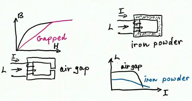
A power inductor commonly uses a ferrite core with an air gap. As current rises, the winding magnetomotive force drives the core material toward saturation; its incremental permeability falls, and the inductance correspondingly decreases.
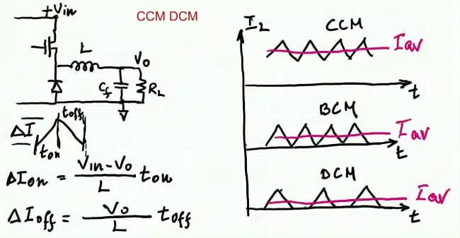
The inductor current ripple is governed by the applied inductor voltage, inductance, and interval duration:
For a conventional gapped ferrite inductor, the inductance can remain relatively constant over part of the current range and then fall quickly as saturation is approached. Powder-core inductors typically show a softer inductance roll-off because their insulated magnetic particles form a distributed air gap, although their high-frequency losses can make ferrite preferable in high-frequency power converters.
Key features and benefits
A current-dependent inductor is not a catalogue component category defined by one universal specification. It is a magnetic design approach in which the core geometry and gap structure are selected to obtain a useful L(I) profile.
- Low inductance at high current can limit component size, copper turns, stored energy requirement, cost, and winding loss.
- Higher inductance at low current reduces current-ripple slope at a fixed switching frequency and conversion ratio.
- A higher low-current inductance can keep a converter in continuous-conduction mode over a wider load range.
- In boundary-conduction operation, higher inductance can enable a lower switching frequency, reducing switching losses.
- Avoiding or delaying discontinuous-conduction mode can reduce current interruption effects that contribute to EMI.
- The desired behaviour is application-specific: the usable current range must remain below severe saturation, where inductance collapses and current stress can escalate rapidly.
Conventional and shaped gaps
An air gap lowers the effective permeability of a ferrite magnetic circuit and increases its energy-storage capability. However, a single conventional gap usually produces a relatively abrupt inductance reduction when the magnetic material approaches saturation.
A shaped or stepped gap provides an alternative. At lower current, flux preferentially follows a low-reluctance section associated with a smaller effective gap. As this section approaches saturation, its permeability reduces and magnetic flux progressively transfers to a path with a larger gap. The result can be an intentionally shaped inductance-current curve.
| Magnetic approach | Typical inductance-current behaviour | Engineering implication |
|---|---|---|
| Conventional single air gap | Approximately constant inductance followed by a relatively sharp drop | Straightforward implementation, but limited control of low-current versus high-current inductance |
| Powder core with distributed gap | More gradual inductance reduction | Soft saturation characteristic, but core loss must be assessed carefully at high switching frequency |
| Stepped or shaped ferrite gap | Tailored transition between higher low-current and lower high-current inductance | Can support mode management, but needs magnetic modelling and mechanical manufacturing control |
A stepped gap should not be treated as a way to operate in deep saturation. Its purpose is to shape the usable incremental-inductance characteristic before the magnetic circuit enters the region where the inductor can no longer provide predictable energy storage.
Buck converter application
In a buck converter, inductor current normally decreases with load current. With fixed switching frequency and input/output voltage, the ripple magnitude remains set principally by the applied inductor voltage, switching interval, and inductance.
At a sufficiently light load, a converter with a fixed low inductance can transition from continuous-conduction mode to boundary-conduction mode and then to discontinuous-conduction mode. In discontinuous conduction, the inductor current reaches zero each switching cycle. This can increase RMS-current-related loss and introduce sharp current transitions that worsen EMI.
A current-dependent inductor can be designed with:
- Lower inductance at higher load current, limiting magnetic size and avoiding the penalty of an unnecessarily large fixed inductance.
- Higher inductance at lower current, reducing ripple and extending the continuous-conduction region.
- A tailored transition region that helps the converter remain near a desirable operating mode over a broader load range.
The trade-off is important. Increasing inductance across the entire load range can suppress ripple, but it normally requires more turns and/or a larger magnetic structure. That increases cost, volume, copper loss, and potentially core loss. A shaped L(I) characteristic aims to avoid paying that penalty at high load current.
Dynamics and control behaviour
The operating mode of a buck converter also affects small-signal response. In general, a converter operating in continuous-conduction mode has different power-stage dynamics from the same converter in discontinuous-conduction mode, and a control loop compensated for one mode may have reduced bandwidth in the other.
The video presentation cites an example in which a stepped-gap inductor had approximately 65 µH at low current and approximately 30 µH at higher current.
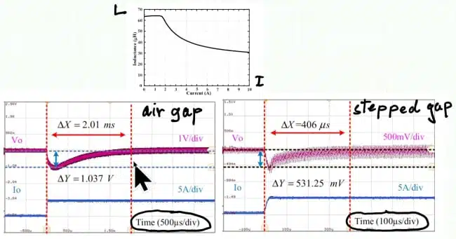
In the illustrated load-step measurements, the stepped-gap arrangement produced a faster output-voltage response and a smaller voltage excursion than the conventional-gap example.
For practical designs, this does not remove the need for normal loop-stability work. The control-to-output transfer function, compensation, load range, mode transitions, current limit, output capacitor characteristics, and thermal operating points should all be verified with the actual non-linear magnetic component.
Active PFC application
Active power-factor-correction inductors carry a low-frequency rectified sinusoidal current with high-frequency switching ripple superimposed. Around the low-current portions of the rectified mains waveform, a fixed-inductance PFC stage may move toward discontinuous conduction.
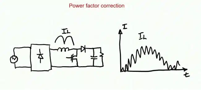
A current-dependent PFC inductor with elevated inductance at low current can reduce the interval in which the converter enters strongly discontinuous operation. This can be beneficial because discontinuous operation in this region can increase distortion and EMI.
The presentation discusses a stepped-gap PFC example comparing conventional and stepped-gap E-core implementations. Reported measurements showed an efficiency improvement of approximately 0.5 percentage points for the stepped-gap configuration in one case, while also emphasizing that the result depends on the chosen gap and complete magnetic design.
For PFC designers, the practical target is not simply the highest low-current inductance. The target is a controlled inductance characteristic that supports the required current waveform, switching-frequency strategy, EMI target, thermal performance, and power-factor requirements without driving the core into an uncontrolled saturation region.
Simulation example
Finite-element analysis shown in the presentation illustrates flux crowding around the lower-reluctance section of a stepped-gap ferrite inductor. As current rises, the local region moves toward saturation, redistributing magnetic flux and reducing inductance.
The illustrated one-turn ferrite example showed the following simulated progression:
| Current | Inductance in the example | Interpretation |
|---|---|---|
| 1 A | 230 µH | Initial high-inductance condition, with flux concentrated in the low-reluctance region |
| 10 A | 200 µH | Increased flux crowding and a moderate inductance decrease |
| 15 A | Approximately half of the initial value | Significant reduction as the local region moves nearer saturation |
| Beyond intended operating range | 50 µH | Broad magnetic saturation and an unsuitable operating condition |
These values describe the specific simulation example in the presentation, not a universal design target or component rating.
Design-in notes for engineers
Define the required L(I) curve
Do not specify only nominal inductance. Define the required minimum incremental inductance across the relevant DC-bias and temperature range, then establish the maximum permissible inductance reduction at peak and fault-related currents.
Useful requirements can include:
- Inductance at zero or low DC bias.
- Inductance at specified normal-load and peak-load currents.
- Saturation or inductance-drop criterion used by the supplier.
- Temperature range and test temperature for every L(I) value.
- AC ripple-current amplitude and switching-frequency range.
- Maximum winding temperature rise and allowed core loss.
- Tolerance of the air-gap geometry and its effect on production spread.
Assess the whole magnetic system
The gap geometry affects more than inductance. Concentrated gaps can create fringing flux, which can raise winding eddy-current loss and contribute to nearby EMI coupling. A stepped design introduces further local flux-density and manufacturing-tolerance considerations.
Verify the following with measurement and, where appropriate, field simulation:
- Core loss under the real DC bias, ripple flux density, temperature, and switching-frequency waveform.
- AC resistance and proximity loss in the winding near the gap.
- Inductance distribution across production tolerances.
- Current-limit margin under low line, overload, startup, and transient conditions.
- Mechanical reproducibility of the stepped or shaped gap.
- Conducted and radiated EMI with the production-intent magnetic assembly.
Work with the control strategy
A non-linear inductor changes ripple amplitude with current and may shift mode-transition boundaries. Current-mode control, valley switching, boundary-mode control, slope compensation, burst operation, and protection thresholds should therefore be checked over the entire intended operating envelope.
Component procurement specifications should also distinguish between a magnetic design that has a useful controlled L(I) profile and an ordinary inductor whose inductance drops unpredictably near saturation. The latter is not a substitute for a purpose-designed current-dependent magnetic component.
Conclusion
Current-dependent inductance can be engineered as a functional characteristic rather than accepted solely as a saturation-related compromise. In buck converters, a high low-current inductance can help retain continuous conduction and support improved light-load behaviour, while a lower high-current inductance can limit magnetic size and loss. In active PFC circuits, a tailored L(I) curve can reduce time spent in strongly discontinuous operation near low-current portions of the mains cycle.
The next step for a practical design is to translate converter-level needs into an explicit inductance-versus-current specification, validate the magnetic structure with simulation and prototype measurements, and confirm control-loop, thermal, and EMI performance using the final production-intent component.
Source
This article is based on the educational video presentation “Current dependent inductors: Overview and applications” by Sam Ben-Yaakov. It adapts the presented examples and concepts into a design-oriented overview; no manufacturer press release or product datasheet was provided with the source material.
Further reading
- Current-Dependent Inductor Modeling and Answer to LTspice Inductor Riddle — A follow-up resource on modelling non-linear, current-dependent inductor behaviour and using it in LTspice simulations.
- Why Power Inductors Use a Ferrite Core With an Air Gap — Explains the role of the air gap in energy storage, saturation margin, AC flux swing, and core-loss control.
- Understanding Inductors With Gapped Cores — A design-oriented introduction to how a deliberate air gap reduces inductance but increases usable current capability and improves predictability.
- Saturation Current of Inductors and Its Measurement — Covers common saturation-current definitions, DC-bias test methods, and interpretation of inductance-drop criteria in datasheets.
- Inductance, Impedance, Q Factor and DCR Losses — Reviews inductance, DCR, AC resistance, Q factor, self-resonant frequency, and saturation considerations in real inductor selection.
- Core Materials, Permeability and Their Losses — Provides background on magnetic-core materials, permeability, and the loss mechanisms relevant to high-frequency power magnetics.
- How to Design an Inductor — A practical design guide covering core selection, gapping, winding choice, DC bias, peak current, and thermal constraints.
- PFC Inductor Magnetic Design Considerations — Relevant supplementary material for readers designing boost-PFC inductors and evaluating PFC magnetic topology choices.