

Power inductor selection requires more than matching nominal inductance and package size. Core material, DC-bias behaviour, winding construction, shielding and thermal limits determine whether a component will perform as intended in a switching converter. These differences also matter when qualifying alternative suppliers or replacing an existing part with a seemingly equivalent device.
Why nominal inductance is not enough
In a buck converter, the power inductor stores magnetic energy as current rises during the switch-on interval and releases energy during the switch-off interval. This action smooths the current delivered to the load and helps establish current ripple for the selected switching frequency and duty cycle.
However, nominal inductance describes only part of the component’s behaviour. Four additional selection factors can become the practical bottleneck:
- DC resistance, or DCR, influences winding loss and temperature rise.
- Saturation current identifies a specified reduction in inductance under DC bias.
- Rated current describes current-carrying capability subject to the manufacturer’s thermal conditions.
- Package size determines the board-space commitment and influences achievable electrical and thermal performance.
The useful starting point is therefore the application’s bottleneck: insufficient inductance under load, excessive heating, limited board space or sensitivity to stray magnetic fields.
Same inductance and package, different usable performance
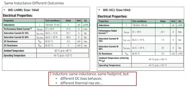
An illustrative comparison between Würth Elektronik WE-LHMI and WE-HCI inductors uses the same nominal inductance of 1 µH and the same 1040 package designation.
| Parameter | WE-LHMI example | WE-HCI example |
|---|---|---|
| Nominal inductance | 1 µH | 1 µH |
| Package designation | 1040 | 1040 |
| Performance rated current | 21.3 A | 23.1 A |
| Saturation current at 10% inductance reduction | 22.7 A | 7.5 A |
| Maximum operating temperature | 125°C | 155°C |
The WE-HCI example has the higher stated performance rated current and maximum operating temperature, while the WE-LHMI example maintains inductance to a substantially higher current at the specified 10% reduction criterion. These are different strengths, not contradictory ratings. Thermal current capability and inductance retention describe separate aspects of suitability.
Ferrite cores: permeability, air gaps and saturation
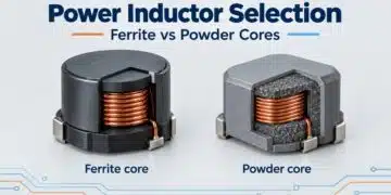
Ferrite and other magnetic core materials provide different combinations of permeability, saturation behaviour and loss. The material families discussed include nickel-zinc and manganese-zinc ferrites, iron-based alloys, and amorphous and nanocrystalline powder structures.
Ferrite cores are ceramic structures produced by pressing and sintering powders containing iron oxide and other metal oxides. Their microstructure influences permeability and core loss, allowing different grades to target different performance priorities. For the shielded drum-core constructions discussed, the magnetic assembly includes a drum core, shielding ring and air gap. The gap is an important design variable for controlling the component’s saturation behaviour.
DC bias and temperature
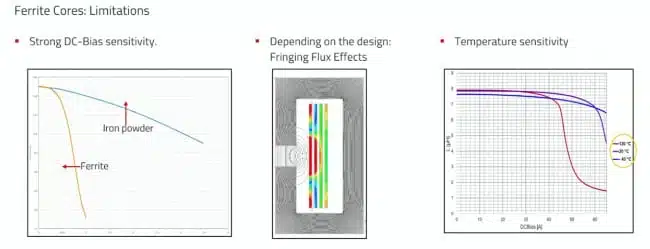
As DC current increases, ferrite inductance can fall relatively sharply near saturation. This behaviour is commonly described as hard saturation. The ferrite comparison includes inductance-versus-current curves at temperatures spanning −40°C to +120°C. The high-temperature curve illustrates why room-temperature behaviour alone is insufficient for assessing the available saturation margin.
The practical selection question is not simply whether an inductor uses ferrite. It is whether the selected component retains sufficient inductance across the application’s current and temperature range.
Air-gap fringing
Magnetic field lines spread outward around an air gap. Depending on the construction and the proximity of conductive material, this fringing field can induce eddy currents and additional local losses. A gap therefore affects more than the saturation characteristic. Its geometry and surrounding layout also influence how the inductor interacts with nearby conductors and components.
Variants within one ferrite family
Würth Elektronik uses WE-PD to illustrate how one ferrite platform can support different priorities:
- The original version provides the baseline construction.
- The performance version targets increased saturation-current capability.
- The robust version targets improved mechanical stability.
The displayed comparison places the performance version highest in saturation-current capability among the versions and reference component shown. This is a comparison of specific examples, not a universal ranking of ferrite technologies.
Mechanical robustness is discussed in terms of maintaining attachment and stability on a PCB exposed to motion or vibration. No quantified vibration, shock or qualification conditions are supplied in the transcript.
Powder cores: gradual inductance roll-off with trade-offs
Powder cores consist of ferromagnetic metal particles insulated from one another and formed into a magnetic body with a binder. The insulation limits electrical conduction between particles and confines eddy-current paths more locally.
Compared with the ferrite examples, the powder-core examples exhibit a more gradual reduction in inductance as DC bias increases. Their inductance-versus-current curves also remain more closely aligned across the illustrated −40°C to +120°C temperature range.
This behaviour can be useful when inductance retention under load is a dominant requirement. It does not mean powder cores have constant inductance or unlimited current capability.
Loss depends on the material and construction
The general comparison identifies higher loss as a powder-core trade-off relative to ferrite. However, there is no universal switching frequency above which all powder cores become unsuitable.
Relevant variables include:
- Alloy composition.
- Particle size and structure.
- Quality of insulation between particles.
- Compaction pressure.
- The finished component’s construction.
WE-MXGI is presented as a lead-frameless molded family optimized for switching frequencies above 1 MHz. Its example loss comparison reports lower AC and DC losses than the reference component shown.
Percolation and mechanical stress
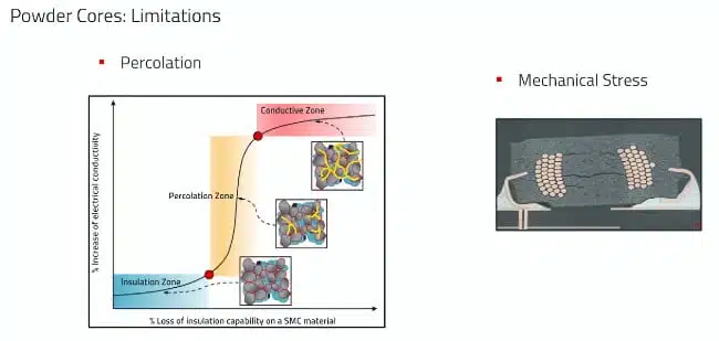
Percolation describes the formation of conductive paths between magnetic particles when their insulation is compromised. Prolonged exposure to excessive temperature is identified as one mechanism that can damage this insulation and increase core loss. Mechanical stress is another limitation: it can deform the winding or cause cracks within the component. These mechanisms support checking the selected component’s operating and handling limits. They do not establish a common failure temperature or lifetime for all powder-core inductors.
Construction matters as much as material
Assembled designs
In assembled constructions, the core is formed separately and the winding is installed in a subsequent process. This approach provides design flexibility. The example also highlights visible solder menisci as an advantage for automated optical inspection. The limitation is miniaturization: winding and assembling a coil onto a preformed core imposes practical manufacturing constraints.
WE-HCI is used as an example of an assembled family employing flat wire. Importantly, the larger 1890 size is discussed in both ferrite and iron-powder versions. A family name alone is therefore not always enough to identify the core material.
Molded designs
In molded constructions, magnetic powder is compressed around a pre-positioned winding. Compaction affects density and permeability, but the manufacturing process must also preserve winding integrity and avoid cracking.
Lead-frame and lead-frameless constructions provide different ways of allocating the internal volume between magnetic material, winding and connection structures. Lead-frameless examples are positioned around more effective use of the available package volume. For selection purposes, “molded” describes a construction approach; it is not, by itself, a complete electrical performance specification.
Winding type
The winding options discussed include:
- Flat wire, associated with lower DCR in the examples.
- Round wire, associated with simpler construction.
- Litz wire, comprising multiple individually insulated strands twisted together for high-frequency applications.
Editorial design guidance: compare finished-component loss data rather than selecting by conductor shape alone. A lower DCR addresses one contributor to heating, while the webinar’s product comparisons also distinguish AC losses.
Package size: electrical gains are not proportional
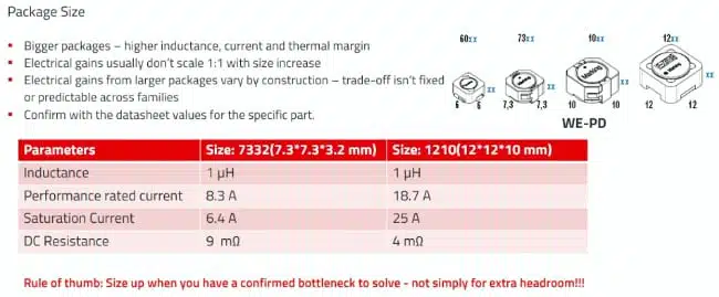
A second illustrative comparison examines two WE-PD package designations, again at 1 µH.
| Parameter | WE-PD 7332 example | WE-PD 1210 example |
|---|---|---|
| Nominal inductance | 1 µH | 1 µH |
| Performance rated current | 8.3 A | 18.7 A |
| Saturation current | 6.4 A | 25 A |
| DC resistance | 9 mΩ | 4 mΩ |
The larger example provides higher stated current capability and lower DCR. However, the gains do not follow a simple proportional relationship with size. The practical lesson is to increase package size to solve a demonstrated limitation, rather than assume that a larger part is automatically the better design choice.
Shielding and application fit
Shielding influences stray magnetic fields and the potential interaction with nearby circuitry. The three constructions discussed are:
- Unshielded: the simplest construction, with the highest stray magnetic field in the comparison.
- Semi-shielded: a compromise using magnetic adhesive to reduce part of the stray field.
- Shielded: a construction intended to minimize stray magnetic fields and suit more EMI-sensitive applications.
For the ferrite construction discussed in the Q&A, the shielding ring is part of the magnetic assembly and is not connected to a PCB pad.
Editorial design guidance: treat shielding as one selection parameter, not as proof that a finished converter will meet its EMI requirements. Verify the selected component in its intended board layout.
Matching the component to the limiting requirement
The examples support several application-oriented priorities:
- For a buck converter with demanding DC-bias requirements, compare inductance retention at the intended current.
- For a thermally constrained design, compare rated-current conditions and component losses.
- For compact, high-frequency DC/DC designs, assess the particular material grade and construction rather than excluding an entire core category.
- For EMI-sensitive circuitry, include shielding and nearby-component interaction in the selection.
- For mechanically demanding assemblies, examine the relevant robust construction and its documented limits.
The discussion does not establish a universally preferred inductor for high-current resonant converters. That choice remains dependent on the actual application requirements.
Design-in notes for engineers
The following checklist is editorial guidance derived from the webinar’s selection framework:
- Define the limiting requirement first: inductance retention, temperature, board space, shielding or mechanical stability.
- Compare saturation currents using the same inductance-reduction criterion. The Q&A discusses both 10% and 30% definitions.
- Review the full inductance-versus-current characteristic where available, not just a single current rating.
- Check magnetic and thermal capability separately. A high saturation-current value does not establish acceptable temperature rise.
- Include operating temperature when evaluating DC-bias margin.
- Compare AC and DC losses under the intended operating conditions; do not rank candidates by DCR alone.
- Verify the exact material and construction of the chosen part, particularly where one family includes multiple variants.
- Increase package size only when the additional space resolves an identified performance limitation.
- Treat ripple-current targets as design inputs rather than fixed rules. The Q&A describes 20–40% as a commonly used range, while making clear that the illustrated 40% setting can be changed.
- Check voltage capability for the exact component. The webinar does not establish a universal voltage rating for power inductors.
- Qualify substitutions against the required electrical, thermal and mechanical behaviour, not only nominal inductance and footprint.
From product family to exact part number
Würth Elektronik’s Product Navigator provides an application- or topology-based entry point into its portfolio.
REDEXPERT then supports comparison using application parameters. The DC-DC Converter Designer described in the webinar can identify a topology from the entered conditions, while a custom mode allows ripple current or target inductance to be specified. The workflow also includes rated-current calculation using default or user-defined PCB trace dimensions.
These tools help translate a design requirement into candidate series and part numbers. The transcript does not provide model-accuracy or validation-error figures, so their results should be treated as design support rather than independent hardware verification.
Conclusion
An appropriate power inductor combines sufficient inductance under load with acceptable loss, temperature, size and magnetic-field behaviour. Ferrite and powder cores offer different strengths, while construction, winding and shielding further shape the result.
For both design-in and purchasing qualification, the decisive comparison is the exact component’s behaviour under the intended operating conditions—not simply its nominal inductance or family label.
Further reading
- Power Inductors and Storage Chokes
- Winding Losses in Transformers and Inductors
- Modeling Fringing Field Losses in Inductors & Transformers
- Power design simulation tools for faster inductor selection
Source
Adapted from Würth Elektronik Group’s webinar, “Power Inductor technologies: Practical Selection and Product Positioning,” published on 29 October 2026. Technical examples and numerical comparisons are drawn from the video transcript; practical recommendations are identified as editorial guidance. Suggested screenshot timestamps correspond to the relevant narrated sections and should be checked when capturing the final frames.
References
- Würth Elektronik Group: Power Inductor technologies: Practical Selection and Product Positioning. Primary technical source and timestamped transcript.