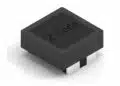




A University of Illinois Chicago and Argonne National Laboratory team led by Rami Rasheedi has characterized commercial power inductors for cryogenic power conversion.
Its study of cryogenic SMD inductors was posted on arXiv on October 20, 2026. The measurements show substantial reductions in winding DC resistance at 4 K, but also expose frequency-dependent limitations that matter more than the abstract’s headline inductance change.
Key takeaways
- Five Vishay SMD power inductors showed measured DC-resistance reductions of approximately 25.7–58.5 times between 300 K and 4 K.
- For the two frequency-characterized devices, the values labeled “DC inductance” fell by approximately 5.0% and 5.5%; at 500 kHz, however, measured inductance fell by approximately 20.4% and 24.2%.
- At 500 kHz, equivalent AC resistance changed from 6.76 Ω to 6.66 Ω for one device and from 3.75 Ω to 4.04 Ω for the other. Cooling therefore did not produce an AC-loss improvement comparable to the DC-resistance improvement.
- A simulated 24 V-to-1 V buck converter using measured inductor impedance reached 86.13% efficiency at 4 K and 3 A for one device, versus 63.60% at 300 K. These are simulation results, not measured converter efficiencies.
Background
Moving power conversion closer to cryogenic electronics can shorten high-current, low-voltage connections. The trade-off is that converter losses then become heat deposited inside the cold environment.
Inductors sit at the center of that trade-off. Lower conductor resistivity reduces DC winding loss, , but magnetic permeability and frequency-dependent losses also change with temperature. A low cold resistance does not guarantee low total loss under switching excitation.
The distinction between inductance, impedance, Q factor and DCR losses is especially important here. The real part of measured inductor impedance includes frequency-dependent winding and magnetic losses; it is not simply the winding’s DC resistance multiplied by a skin-effect correction.
The preprint positions its contribution between earlier cryogenic RF-component measurements and studies of bare or custom-wound magnetic cores. Its practical focus is packaged, commercially available power inductors rather than a newly developed magnetic material.
What the researchers found
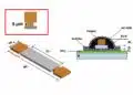
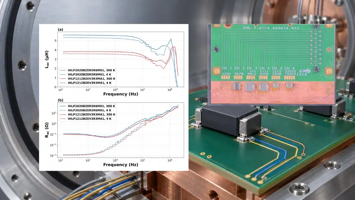
The team mounted five Vishay inductors on a custom four-wire test board and cooled them in a Denali ADR cryostat. A resistance bridge monitored DC resistance during cooldown. Lock-in measurements extracted complex impedance, with frequency sweeps extending to 2 MHz for two selected devices.
For AC characterization, a 10 Ω reference resistor established excitation current. The measured DUT voltage then yielded impedance, equivalent resistance and inductance. The paper does not report a statistical population of repeated samples for each part number.
Resistance improvement versus frequency-dependent inductance
The following values come from Table III. Percentage changes are recalculated from its tabulated measurements.
| Parameter and measurement condition | IHLP2020BZER5R6M01, 300 K → 4 K | IHLP1212BZEV3R3MA1, 300 K → 4 K |
|---|---|---|
| Measured DC resistance | 113.944 → 1.948 mΩ | 93.223 → 2.978 mΩ |
| DC-resistance reduction factor | 58.49× | 31.30× |
| Inductance labeled “DC”; extraction frequency unspecified | 5.59 → 5.31 µH; −5.0% | 3.79 → 3.58 µH; −5.5% |
| AC inductance at 500 kHz; excitation amplitude and DC bias unspecified | 4.42 → 3.52 µH; −20.4% | 2.89 → 2.19 µH; −24.2% |
| Equivalent AC resistance at 500 kHz; same reporting limitations | 6.76 → 6.66 Ω; −1.5% | 3.75 → 4.04 Ω; +7.7% |
The operating-frequency result is more consequential than the low-frequency headline. At 500 kHz, both devices lose appreciably more inductance than the approximately 5–5.5% emphasized in the abstract.
Likewise, the large increase in partly reflects the collapsing denominator. It should not be read as an equivalent multiplication of absolute AC resistance.
Converter results remain model-dependent
The team imported measured impedance into Cadence Spectre as a one-port Touchstone representation. The simulated buck converter operated from 24 V to 1 V at loads of 1, 2 and 3 A, targeting 0.5 A peak-to-peak inductor-current ripple.
For the IHLP2020BZER5R6M01, simulated full-converter efficiency increased from 65.25% to 70.50% at 1 A and from 63.60% to 86.13% at 3 A when moving from 300 K to 4 K. The corresponding improvements are 5.25 and 22.53 percentage points.
These gains do not isolate the inductors alone. The model also assumes an 80% reduction in GaN-switch on-resistance at 4 K, extrapolated from published measurements of a comparable device. Other temperature-dependent switch parameters retain their room-temperature values.
Why it matters for passive components
The direct relevance is to power inductors supplying cryogenic support electronics, not to all passive-component families or all temperature stages of a quantum system.
The measurements support a useful screening principle: commercial packaged inductors can retain substantial inductance while their winding resistance falls sharply at 4 K. At higher DC current, the resulting conduction-loss reduction can dominate the modeled loss balance.
However, switching-frequency impedance must remain part of selection. The measured inductance decline at 500 kHz can affect ripple and control behavior, while AC losses remain significant after DC winding loss becomes small.
The broader passive-component requirements in quantum computing also include magnetic compatibility, noise and mounting reliability. This experiment does not establish that a magnetic-core power inductor can be placed close to sensitive qubits.
For sourcing teams, the findings justify investigating the tested part numbers—not approving substitutions across nominally similar product families. Core composition, winding construction and package thermal paths are not characterized sufficiently to generalize the results.
From lab to component
An editorial maturity estimate is TRL 3–4 for the proposed cryogenic power-conversion application: experimental component characterization combined with converter simulation, rather than a demonstrated operating converter.
Several gaps separate this result from qualification.
First, the paper does not establish inductance or loss under the full combination of DC bias, ripple amplitude and temperature used in its converter analysis. A linear impedance representation cannot independently validate saturation or large-signal magnetic loss.
Second, self-heating remains unresolved experimentally. The paper estimates approximately 0.2–0.25 W of inductor dissipation at 4 K and discusses thermal coupling sufficient to keep the component within its low-resistance temperature regime. That is not a demonstration that a powered winding and core remain at 4 K.
Third, there are no reported endurance results, repeated thermal-cycle qualification or lot-to-lot statistics. Commercial availability of the starting components should not be confused with manufacturer qualification for this environment.
Finally, converter efficiency alone does not establish system-level energy benefit. The study does not close the balance among avoided interconnect losses, heat deposited at the cold stage and refrigeration power.
What engineers should watch: cryogenic SMD inductors
- Operating-point characterization: inductance and loss measured with representative DC current and switching ripple, not only unspecified small-signal excitation.
- Frequency coverage: documented handling of current harmonics beyond the measured 2 MHz impedance range.
- Powered thermal measurements: winding, core and board temperatures during sustained conversion.
- Repeatability: multiple units, production lots, cooldowns and uncertainty bounds for resistance and phase measurements.
- Hardware validation: measured converter efficiency using cryogenically characterized switches, capacitors and control circuitry.
- Qualification evidence: thermal cycling, package integrity, insulation stability and manufacturer-backed operating limits.
Summary
The study demonstrates a strong reduction in DC winding resistance for five commercial SMD power inductors at 4 K. For two devices, frequency-dependent measurements also show that meaningful inductance remains, but operating-frequency inductance changes and AC losses are substantially less favorable than the DC results alone imply.
The practical takeaway is to evaluate cold inductors through impedance, bias and thermal behavior together. The preprint provides useful candidate data for prototype work, not a qualified cryogenic component specification.
Further reading
- TDK technical note How to Use Power Inductors
- EEE Components Qualification Challenges and Approaches for Cryogenic Temperature
Source
This article is based on the openly accessible arXiv preprint, not a verified peer-reviewed journal publication. No matching institutional press release was found, and the accessible source record did not establish the reuse license; open availability should not be interpreted as a Creative Commons reuse grant. These are research results obtained from commercial components, not qualified cryogenic specifications: design decisions should await manufacturer data and application-specific qualification.
References
- Rami Rasheedi, Umeshkumar Patel, Jonathan Baldwin, Antonino Miceli and Inna Partin-Vaisband, “Experimental Characterization of SMD Inductors for Cryogenic Power Conversion at 4 K,” arXiv, arXiv:2610.28923v1 [eess.SY], October 20, 2026, https://doi.org/10.48550/arXiv.2610.28923. Preprint; no journal volume, issue or article number identified. Open repository access; reuse license unconfirmed. Full-text measurements, methods, simulations and acknowledgments were available in the indexed PDF text; the DOI resolved to the repository record.