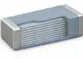


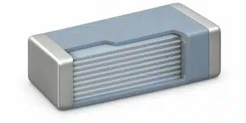




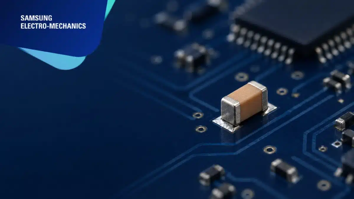
Samsung Electro-Mechanics has introduced the CL05Z106MS66PN# automotive multilayer ceramic capacitor, combining 10 µF nominal capacitance and a 2.5 V rating in a 0402-inch package measuring 1.0 × 0.5 mm.
The Samsung Electro-Mechanics device extends the automotive X7T MLCC range for ADAS electronics, where SoC power requirements and restricted mounting space drive capacitor selection.
Key features and benefits
- 10 µF nominal capacitance in a 0402-inch / 1005-metric case.
- 2.5 V rated voltage for low-voltage circuit positions.
- X7T temperature characteristic covering −55 °C to +125 °C.
- Automotive product meeting AEC-Q200 requirements.
- Mass production underway, with samples and technical support available.
- Related 0603-inch devices provide 22 µF at rated voltages of 2.5 V and 4 V.
Technical highlights
The new combination is 10 µF at 2.5 V in the 0402-inch case. The associated 22 µF products use a 0603-inch / 1608-metric case with nominal length and width of 1.6 × 0.8 mm.
| Part number | Case size, inch / metric | Nominal capacitance | Rated voltage |
|---|---|---|---|
| CL05Z106MS66PN# | 0402 / 1005 | 10 µF | 2.5 V |
| CL10Z226MS96PN# | 0603 / 1608 | 22 µF | 2.5 V DC |
| CL10Z226MR96PN# | 0603 / 1608 | 22 µF | 4 V DC |
All three devices have X7T temperature characteristics and are in mass production. The two 0603 devices have ±20% capacitance tolerance and length, width and thickness dimensions of 1.60 ±0.20 × 0.80 ±0.20 × 0.80 ±0.20 mm. The “#” suffix denotes the packaging code.
Temperature behaviour and effective capacitance
X7T permits a temperature-related capacitance change of −33% to +22% across −55 °C to +125 °C. This temperature characteristic is distinct from initial capacitance tolerance and does not represent the capacitance retained under DC operating voltage.
Class II MLCC capacitance decreases with applied DC voltage. The DC bias characteristics of ceramic capacitors therefore matter when translating the 10 µF nominal value into a decoupling requirement. Applied voltage, temperature and AC signal level should be considered together when establishing the effective capacitance available in circuit.
Impedance also governs decoupling performance. An MLCC includes equivalent series resistance and equivalent series inductance alongside its capacitance. Its response changes with frequency, so nominal capacitance alone does not determine how effectively it suppresses power-rail noise.
Typical applications and application fit
Target applications include automotive ADAS electronics, sensors, radar systems and SoC power networks. The 10 µF, 2.5 V device addresses low-voltage capacitor positions where a 1.0 × 0.5 mm body is relevant to the placement budget.
For SoC supply decoupling, selection should begin with the required effective capacitance and power-network impedance at the operating voltage. The 0402 device combines the 10 µF nominal value with the smaller case; the related 0603 devices provide 22 µF nominal capacitance, including a 4 V option. These are separate electrical and mechanical choices rather than interchangeable footprints.
The X7T temperature range supports selection for electronics operating between −55 °C and +125 °C. Local component temperature and temperature-dependent capacitance remain part of the circuit assessment, particularly near heat-generating processors and power-management devices.
Design-in notes for engineers
- Match the operating voltage to the selected 2.5 V or 4 V rating. Include voltage excursions in the electrical assessment rather than selecting from the nominal rail voltage alone.
- Establish the required effective capacitance at the applied DC voltage, temperature and AC signal level. Keep the X7T temperature window separate from initial tolerance.
- Assess impedance over the frequencies relevant to the power network. Place decoupling MLCCs close to the supplied IC to limit the inductance of the connection.
- Match the PCB footprint and assembly clearances to the selected case dimensions. A 0402 device and a 0603 device require different layout provisions.
- Validate final selection under the actual electrical, thermal and assembly conditions before production release.
Further reading
- Samsung Electro-Mechanics Releases 0201 X7T 1uF 6.3V MLCC for ADAS Applications
- Samsung Introduces Automotive 1206 100uF X7T MLCC for Power Rails in ADAS and SoCs
Source
This article is based on the Samsung Electro-Mechanics product announcement and official product documentation. Engineers should refer to the current manufacturer datasheet for final design and qualification.
References
- Samsung Electro-Mechanics Launches an Ultra-High-Capacitance MLCC for ADAS (0402 inch, X7T, 10uF, 2.5V), Samsung Electro-Mechanics, 21 October 2026.
- CL10Z226MS96PN# — MLCC Product Information, Samsung Electro-Mechanics.
- CL10Z226MR96PN# — MLCC Product Information, Samsung Electro-Mechanics.
- Multilayer Ceramic Capacitors — Part II: Automotive, Samsung Electro-Mechanics, December 2025.
- Product FAQ, Samsung Electro-Mechanics.