











Passive Components Blog
No Result
View All Result
  • Home
  • News
    • All
    • Aerospace & Defence
    • Antenna
    • Applications
    • Automotive
    • Capacitors
    • Circuit Protection Devices
    • electro-mechanical news
    • Filters
    • Fuses
    • Inductors
    • Industrial
    • Integrated Passives
    • inter-connect news
    • Market & Supply Chain
    • Market Insights
    • Medical
    • Modelling and Simulation
    • New Materials & Supply
    • New Technologies
    • Non-linear Passives
    • Oscillators
    • Passive Sensors News
    • Resistors
    • RF & Microwave
    • Telecommunication
    • Weekly Digest

    Vishay IFBT SMT Flyback Transformers Target PoE and Isolated DC/DC Designs up to 30 W

    Bourns Automotive BMS Signal Transformer Combines Reinforced Isolation and Common-Mode Noise Rejection

    Murata Launches 100V 10 µF Lead-Type MLCCs for 48V Systems

    Bourns Extends Current Sense Resistors for High-Current Power Designs with 0.1 mΩ, 15 W

    KYOCERA AVX Releases Vibration-Proof SMD Aluminum Electrolytic Capacitors for Harsh Industrial Designs

    Vishay Introduces Automotive Low Loss SMD Common-Mode Chokes

    YAGEO Adds X8 Flexible-Termination Automotive MLCCs for 150°C Designs

    Current-Dependent Inductors: Using Non-Linear Inductance in Buck Converters and PFC Stages

    Vishay Releases High-Power Thick Film Resistors for Compact Power Modules

    Trending Tags

    • Ripple Current
    • RF
    • Leakage Current
    • Tantalum vs Ceramic
    • Snubber
    • Low ESR
    • Feedthrough
    • Derating
    • Dielectric Constant
    • New Products
    • Market Reports
  • Knowledge Blog
  • Dossiers
    • AI Hardware Dossier
    • Automotive Dossier
    • Industrial Robotics Dossier
    • Power Converter Dossier
    • Capacitor Dossier
    • Resistor Dossier
    • Inductor Dossier
    • Circuit Protection Dossier
  • Suppliers
    • Who is Who
  • PCNS
    • PCNS 2025
    • PCNS 2023
    • PCNS 2021
    • PCNS 2019
    • PCNS 2017
  • Events
  • Home
  • News
    • All
    • Aerospace & Defence
    • Antenna
    • Applications
    • Automotive
    • Capacitors
    • Circuit Protection Devices
    • electro-mechanical news
    • Filters
    • Fuses
    • Inductors
    • Industrial
    • Integrated Passives
    • inter-connect news
    • Market & Supply Chain
    • Market Insights
    • Medical
    • Modelling and Simulation
    • New Materials & Supply
    • New Technologies
    • Non-linear Passives
    • Oscillators
    • Passive Sensors News
    • Resistors
    • RF & Microwave
    • Telecommunication
    • Weekly Digest

    Vishay IFBT SMT Flyback Transformers Target PoE and Isolated DC/DC Designs up to 30 W

    Bourns Automotive BMS Signal Transformer Combines Reinforced Isolation and Common-Mode Noise Rejection

    Murata Launches 100V 10 µF Lead-Type MLCCs for 48V Systems

    Bourns Extends Current Sense Resistors for High-Current Power Designs with 0.1 mΩ, 15 W

    KYOCERA AVX Releases Vibration-Proof SMD Aluminum Electrolytic Capacitors for Harsh Industrial Designs

    Vishay Introduces Automotive Low Loss SMD Common-Mode Chokes

    YAGEO Adds X8 Flexible-Termination Automotive MLCCs for 150°C Designs

    Current-Dependent Inductors: Using Non-Linear Inductance in Buck Converters and PFC Stages

    Vishay Releases High-Power Thick Film Resistors for Compact Power Modules

    Trending Tags

    • Ripple Current
    • RF
    • Leakage Current
    • Tantalum vs Ceramic
    • Snubber
    • Low ESR
    • Feedthrough
    • Derating
    • Dielectric Constant
    • New Products
    • Market Reports
  • Knowledge Blog
  • Dossiers
    • AI Hardware Dossier
    • Automotive Dossier
    • Industrial Robotics Dossier
    • Power Converter Dossier
    • Capacitor Dossier
    • Resistor Dossier
    • Inductor Dossier
    • Circuit Protection Dossier
  • Suppliers
    • Who is Who
  • PCNS
    • PCNS 2025
    • PCNS 2023
    • PCNS 2021
    • PCNS 2019
    • PCNS 2017
  • Events
No Result
View All Result
Passive Components Blog
No Result
View All Result

Vishay IFBT SMT Flyback Transformers Target PoE and Isolated DC/DC Designs up to 30 W

28.8.2026
Reading Time: 6 mins read
A A

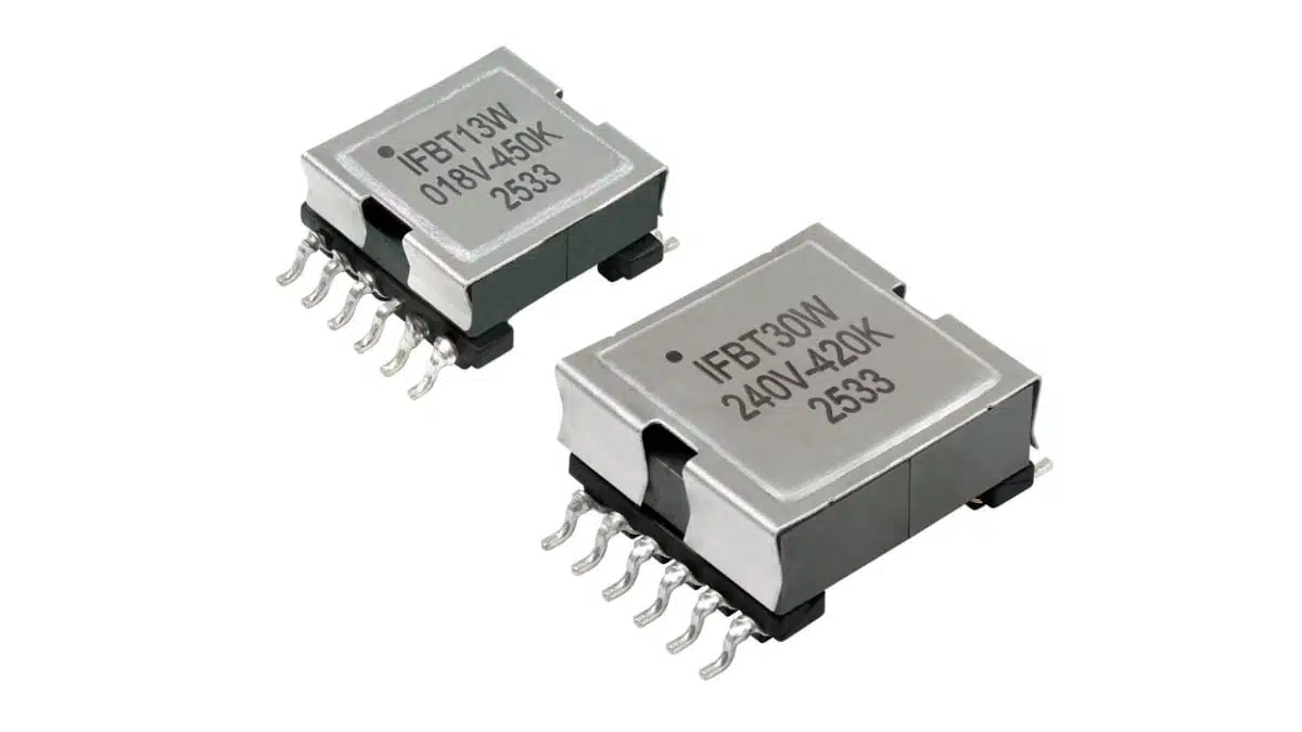
Vishay has introduced the IFBT series of surface-mount flyback transformers for isolated power converters operating from a 26 V to 72 V input range at 250 kHz.

The Vishay IFBT MT Flyback Transformers family combines configurable multiple windings with 1500 VRMS isolation, addressing PoE power stages and isolated DC/DC converter designs up to 30 W.

RelatedPosts

Vishay Introduces Automotive Low Loss SMD Common-Mode Chokes

Vishay Releases High-Power Thick Film Resistors for Compact Power Modules

Vishay Introduces Y1 SMD Ceramic Disc Safety Capacitors to Reduce EMI Filter Board Space

Key features and benefits

  • Surface-mount flyback transformer family for compact isolated power-conversion assemblies, with package dimensions starting at 22.0 mm × 17.5 mm × 9.1 mm.
  • 17 standard devices spanning 6 W, 13 W, and 30 W power options.
  • 26 V to 72 V input operation at 250 kHz, matching a broad range of intermediate-bus and PoE-related converter requirements.
  • 1500 VRMS isolation for 60 seconds from the primary and bias windings to the secondary, supporting galvanic separation between input and load domains.
  • Multiple windings that can be connected in series or parallel, giving designers options to tailor voltage or current capability to the converter architecture.
  • Open construction intended to simplify winding modifications for customer-specific requirements.
  • RoHS-compliant construction and a specified operating temperature range from -40 °C to +125 °C.

Technical highlights

The IFBT family covers primary inductance values from 35 µH to 75 µH, with a ±10% tolerance. Maximum peak-current ratings range from 1.1 A to 2.6 A, depending on the part number and power class.

ParameterIFBT series range or option
Input voltage range26 V to 72 V
Nominal operating frequency250 kHz
Isolation1500 VRMS for 60 s, primary and bias to secondary
Primary inductance35 µH to 75 µH, ±10%
Output-voltage options1.8 V to 24 V
Output-current options0.5 A to 9.0 A
Maximum peak current1.1 A to 2.6 A
Temperature range-40 °C to +125 °C
Starting package size22.0 mm × 17.5 mm × 9.1 mm

The published standard options cover low-voltage outputs such as 1.8 V, 2.5 V, 3.3 V and 5 V, along with 12 V, 19.5 V and 24 V outputs. This range is relevant where a converter must derive isolated logic, control, communication or load rails from a higher-voltage distribution bus.

Selected 30 W options

Part numberPrimary inductanceMaximum peak currentNominal output
IFBT0912ABFS303R3042 µH2.6 A3.3 V / 9.0 A
IFBT0912ABFS305R0042 µH2.6 A5.0 V / 6.0 A
IFBT0912ABFS30120042 µH2.6 A12 V / 2.5 A
IFBT0912ABFS30200042 µH2.6 A19.5 V / 1.5 A
IFBT0912ABFS30240042 µH2.6 A24 V / 1.25 A

Typical applications

Vishay positions the IFBT transformers for:

  • 6 W and 30 W Power over Ethernet designs
  • Isolated DC/DC converters up to 30 W
  • Automotive lighting LED drivers
  • Energy-generation, distribution and management equipment
  • Industrial drives, tools and automation systems
  • Home and building controls
  • Consumer and white-goods electronics
  • Telecom equipment
  • Medical instrumentation

Application fit

A flyback transformer stores energy in its magnetising inductance while the primary-side switch is on, then transfers that energy to the secondary when the switch turns off. This makes the topology particularly useful for isolated low- and medium-power rails, multiple outputs, and applications where a transformer must also provide safety or functional isolation. For a practical overview of topology operation and magnetic-component requirements, see Flyback Transformer Understanding and Design.

The IFBT winding flexibility can be useful when adapting a standard magnetic platform to an output-voltage or load-current requirement. However, a winding change should be treated as a full magnetic and safety review rather than a simple turns-ratio adjustment, because it can affect leakage inductance, winding capacitance, regulation, peak current, thermal performance and isolation distances.

Design-in notes for engineers

  • Verify the operating point. The 26 V to 72 V input range and 250 kHz operating point should be checked against the actual controller frequency, input transient profile and required output-power envelope.
  • Select by converter energy requirements, not output voltage alone. Compare the primary inductance, peak-current rating, turns ratio, winding DCR and thermal conditions with the intended discontinuous, critical or continuous-conduction operating mode.
  • Account for leakage inductance. Leakage inductance influences drain-voltage overshoot and the energy handled by the clamp or snubber network; its impact should be evaluated with the selected MOSFET, rectifier and PCB layout.
  • Check isolation at system level. The stated 1500 VRMS test condition defines transformer isolation performance, but the complete converter must still meet applicable creepage, clearance, insulation-system and end-equipment safety requirements.
  • Evaluate winding configuration carefully. Series and parallel winding arrangements can change output-current capability and voltage stress, but they require correct phasing, current sharing and insulation review.
  • Validate temperature rise. The specified -40 °C to +125 °C range does not replace transformer temperature-rise testing in the final enclosure, particularly in sealed industrial, telecom, lighting and PoE equipment.
  • Qualify custom variants early. Vishay states that the open construction supports winding modifications; designers should obtain the current manufacturer datasheet and documentation for final electrical, mechanical and production qualification.

For circuit-level context, the Flyback Converter Design and Calculation guide provides a useful starting point for relating reflected voltage, duty cycle, primary inductance and switch-current stress.

Further reading

  • Flyback Transformer Understanding and Design
  • Common Mistakes in Flyback Transformer Specs
  • How to design a 60W Flyback Transformer
  • USB PD 3.0 Flyback Transformer Optimisation
  • Transformers: How Transformers and Solenoids Work

Source

This article is based on the Vishay manufacturer press release and product information for the IFBT series. Engineers should consult the current manufacturer datasheet and supporting documentation for final component selection, qualification and design release.


References

  1. Vishay press release: IFBT Surface-Mount Flyback Transformers
  2. Vishay IFBT product family overview
  3. Vishay IFBT datasheet

Related

Recent Posts

Bourns Automotive BMS Signal Transformer Combines Reinforced Isolation and Common-Mode Noise Rejection

27.8.2026
19

Murata Launches 100V 10 µF Lead-Type MLCCs for 48V Systems

27.8.2026
27

Bourns Extends Current Sense Resistors for High-Current Power Designs with 0.1 mΩ, 15 W

26.8.2026
30

KYOCERA AVX Releases Vibration-Proof SMD Aluminum Electrolytic Capacitors for Harsh Industrial Designs

26.8.2026
32

Vishay Introduces Automotive Low Loss SMD Common-Mode Chokes

26.8.2026
24

YAGEO Adds X8 Flexible-Termination Automotive MLCCs for 150°C Designs

25.8.2026
55

Current-Dependent Inductors: Using Non-Linear Inductance in Buck Converters and PFC Stages

24.8.2026
33

Vishay Releases High-Power Thick Film Resistors for Compact Power Modules

24.8.2026
23

Passive Components for Industrial Automation and Robotics (Dossier Report 08/26)

20.8.2026
105

Upcoming Events

Sep 10
11:00 - 12:00 CEST

Equipment models and model strategies for Space Missions

Sep 29
16:00 - 17:00 CEST

Cybersecurity 2026

Nov 24
16:00 - 17:00 CET

Component selection with the WE REDEXPERT® DC-DC Converter Designer Tool

View Calendar

Popular Posts

  • Buck Converter Design and Calculation

    0 shares
    Share 0 Tweet 0
  • Boost Converter Design and Calculation

    0 shares
    Share 0 Tweet 0
  • LLC Resonant Converter Design and Calculation

    0 shares
    Share 0 Tweet 0
  • Earthing Systems and IEC Classification Explained

    0 shares
    Share 0 Tweet 0
  • MLCC and Ceramic Capacitors

    0 shares
    Share 0 Tweet 0
  • Flyback Converter Design and Calculation

    0 shares
    Share 0 Tweet 0
  • MLCCs in the Age of AI: Q2 2026 Market Tightness

    0 shares
    Share 0 Tweet 0
  • Audio Capacitors: Choosing Capacitors for Crossover Circuits

    0 shares
    Share 0 Tweet 0
  • Capacitor Charging and Discharging

    0 shares
    Share 0 Tweet 0
  • Thermistors Basics, NTC and PTC Thermistors

    0 shares
    Share 0 Tweet 0

Newsletter Subscription


Passive Components Blog

© 2015–2026
All rights reserved

  • Home
  • Privacy Policy
  • EPCI Membership & Advertisement
  • About

No Result
View All Result
  • Home
  • Knowledge Blog
  • Dossiers
  • PCNS

© 2015–2026
All rights reserved










