



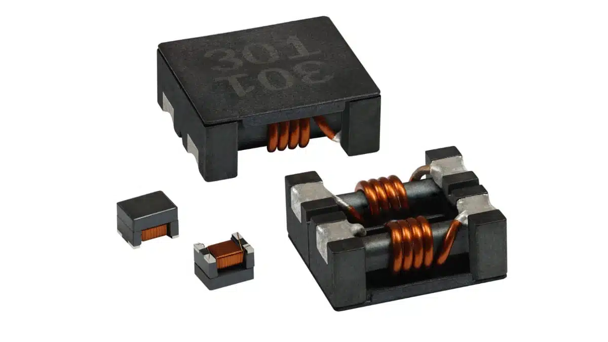
Vishay has introduced four automotive-grade surface-mount common-mode chokes spanning high-current power-line filtering and compact signal-/low-current EMI suppression.
The Vishay common-mode chokes ICM5050-A, ICM6050-A, IFLN-1210BE-A, and IFLN-1812CZ-A combine low DC resistance with common-mode impedance options for automotive DC/DC converters, displays, lighting drivers, in-vehicle networks, and battery-powered electronics.
Key features and benefits
- Four AEC-Q200-qualified SMD common-mode choke families: ICM5050-A, ICM6050-A, IFLN-1210BE-A, and IFLN-1812CZ-A.
- Low DCR for reduced conduction loss: depending on family and value, maximum DCR ranges from 0.4 mΩ to 12 mΩ. This is particularly relevant on power rails where DC current flows continuously through both windings.
- Two current-capable wirewound ferrite options: ICM5050-A supports heat-rating current up to 11 A, while ICM6050-A reaches 14 A.
- Two compact high-impedance precision-wound options: IFLN-1210BE-A and IFLN-1812CZ-A provide common-mode impedance up to 11 kΩ at 100 MHz in packages as small as 3.2 mm × 2.5 mm × 2.5 mm.
- Automotive temperature capability: the IFLN series is specified from -55 °C to +150 °C; the larger ICM parts operate from -40 °C to +125 °C.
- Assembly-ready construction: all four series are RoHS-compliant, halogen-free, compatible with reflow soldering, and suitable for automated pick-and-place assembly.
A common-mode choke attenuates noise currents flowing in the same direction on a conductor pair while ideally presenting little impedance to the intended differential current or signal. That operating principle makes it a practical EMI-control component where conducted emissions must be managed without imposing an excessive DC voltage drop.
Technical highlights
| Series | Construction and package | Common-mode impedance, typical | Maximum DCR | Heat-rating current, typical | Operating temperature |
|---|---|---|---|---|---|
| ICM5050-A | Wirewound ferrite, 12.0 mm × 11.0 mm × 6.0 mm | 160 Ω to 850 Ω at 10 MHz; 500 Ω to 1700 Ω at 100 MHz | 4 mΩ to 12 mΩ | 5.5 A to 11 A | -40 °C to +125 °C |
| ICM6050-A | Wirewound ferrite, 15.0 mm × 13.0 mm × 6.0 mm | 40 Ω to 80 Ω at 10 MHz; 300 Ω to 700 Ω at 100 MHz | 3.5 mΩ to 5 mΩ | 10 A to 14 A | -40 °C to +125 °C |
| IFLN-1210BE-A | Precision-wound ferrite, 3.2 mm × 2.5 mm × 2.5 mm | 550 Ω to 5100 Ω at 10 MHz; 2200 Ω to 11,000 Ω at 100 MHz | 0.4 mΩ to 1.5 mΩ | 0.150 A to 0.300 A | -55 °C to +150 °C |
| IFLN-1812CZ-A | Precision-wound ferrite, 4.5 mm × 3.2 mm × 3.0 mm | 600 Ω to 5800 Ω at 10 MHz; 4000 Ω to 5200 Ω at 100 MHz | 0.6 mΩ to 2 mΩ | 0.200 A to 0.360 A | -55 °C to +150 °C |
For the ICM5050-A and ICM6050-A, Vishay defines the stated heat-rating current as the DC current causing an approximate 40 °C temperature rise. The current values for the IFLN-1210BE-A and IFLN-1812CZ-A correspond to an approximate 20 °C temperature rise, so engineers should not compare the current figures across all four families without accounting for those different test conditions.
The large ICM packages address higher-current rails where low DCR is important for efficiency. Vishay positions them as potential alternatives to much larger toroidal common-mode chokes, while retaining surface-mount assembly compatibility.
Typical applications
Vishay identifies the new chokes for:
- DC/DC power supplies and converter input or output lines
- LCD displays and display supply rails
- Automotive lighting drivers
- CAN, LAN, and in-vehicle Ethernet networks
- Battery-powered devices
- General noise suppression and filtering functions
The ICM5050-A and ICM6050-A are the more natural candidates for power-line filtering in compact automotive power stages, including auxiliary converters and higher-current electronic modules. The IFLN-1210BE-A and IFLN-1812CZ-A are better aligned with lower-current lines requiring high impedance in the VHF range, including network interfaces and locally filtered supply branches.
Application fit
| Design requirement | More suitable family | Selection rationale |
|---|---|---|
| High DC current with low insertion loss | ICM5050-A or ICM6050-A | Heat-rating current reaches 11 A and 14 A respectively, with milliohm-class DCR |
| Compact filter for high-frequency common-mode noise | IFLN-1210BE-A or IFLN-1812CZ-A | High common-mode impedance is available at 100 MHz in very small SMD packages |
| Automotive electronics exposed to +150 °C ambient conditions | IFLN-1210BE-A or IFLN-1812CZ-A | These series specify operation through +150 °C |
| Automotive DC/DC converter or power rail | ICM5050-A or ICM6050-A | Higher current capability suits power-path use, subject to full thermal validation |
| CAN, LAN, or Ethernet noise control | IFLN-1210BE-A or IFLN-1812CZ-A | Vishay specifically identifies CAN and LAN EMI suppression for the precision-wound families |
Design-in notes for engineers
- Start with the noise spectrum, not nominal inductance alone. Check the impedance-versus-frequency curve against the measured or expected disturbance band. A choke that is effective near 100 MHz may not provide the required attenuation at a lower switching-frequency harmonic.
- Use the correct current definition. The published heat-rating currents are tied to specific allowable temperature rises; validate winding temperature at the worst-case ambient temperature, airflow condition, copper layout, and continuous current.
- Calculate DCR heating in the real current path. In first order, resistive dissipation is P=I2R. Low DCR can materially reduce loss on multi-ampere automotive rails, but connector, PCB-trace, and via resistance should be evaluated at the same time.
- Check differential-mode behavior separately. A common-mode choke primarily targets common-mode current. If the emissions problem contains substantial differential-mode energy, the complete filter may also require a differential inductor, capacitors, damping, or layout changes.
- Protect the filter layout. Place the choke close to the relevant cable, connector, or noise boundary, minimize the loop area around shunt capacitors, and avoid routing noisy switching nodes alongside the filtered side. These practical measures are central to effective EMI filter design in power electronics.
- Evaluate data-line signal integrity. For CAN, LAN, and Ethernet interfaces, confirm differential insertion loss, return loss, common-mode conversion, isolation requirements, and the relevant interface standard according to the manufacturer datasheet.
- Treat qualification as one element of release. AEC-Q200 qualification supports automotive passive-component robustness screening, but system-level validation still needs to cover the end-use environment, solder-joint reliability, transient exposure, EMC compliance, and sourcing requirements.
- Confirm final ordering codes and availability. Vishay states that samples and production quantities are available, with reported lead times of 10 to 12 weeks; verify current commercial status and approved-source requirements before production release.
Further reading
- A Guide to Understanding Common Mode Choke
- EMI Filters in Power Electronics
- What Are EMI Filters?
- EMC Filters Design – from Component to Design
Source
This article is based on Vishay Intertechnology’s manufacturer press release and associated official product information for the ICM5050-A, ICM6050-A, IFLN-1210BE-A, and IFLN-1812CZ-A series. Engineers should consult the current manufacturer datasheet and qualification documentation for final component selection, PCB footprinting, thermal assessment, and design release.