Passive Components Blog
No Result
View All Result
  • Home
  • NewsFilter
    • All
    • Aerospace & Defence
    • Antenna
    • Applications
    • Automotive
    • Capacitors
    • Circuit Protection Devices
    • electro-mechanical news
    • Filters
    • Fuses
    • Inductors
    • Industrial
    • Integrated Passives
    • inter-connect news
    • Market & Supply Chain
    • Market Insights
    • Medical
    • Modelling and Simulation
    • New Materials & Supply
    • New Technologies
    • Non-linear Passives
    • Oscillators
    • Passive Sensors News
    • Resistors
    • RF & Microwave
    • Telecommunication
    • Weekly Digest

    Researchers Demonstrated High Energy Ceramic Capacitors Stable in Wide Temperature Range

    Stackpole Offers High Voltage Plate Resistors up to 40KV

    How to Manage Supercapacitors Leakage Current and Self Discharge 

    Qualification of Commercial Supercapacitors for Space Applications

    Experimental Evaluation of Wear Failures in SMD Inductors

    Resonant Capacitors in High-Power Resonant Circuits

    a Schematic diagram of the BNT-based components constructed based on the entropy-increase strategy. b Digital photograph, cross-sectional SEM image, and EDS mappings of the MLCCs. c Unipolar P-E loops of MLCCs as a function of applied E. d Wrec and η of the MLCCs as a function of applied E. The comparison of (e) Wrec and η, (f) η and UF of the MLCCs with those of other recently reported state-of-the-art MLCCs. source: Nature Communications

    Researchers Proposed Enhanced Energy Storage MLCC

    Littelfuse Releases First Reflow-Compatible Illuminated Tactile Switch

    Vishay Unveils 5W Power Metal Strip Resistor in Compact 1206 Case Size

    Trending Tags

    • Ripple Current
    • RF
    • Leakage Current
    • Tantalum vs Ceramic
    • Snubber
    • Low ESR
    • Feedthrough
    • Derating
    • Dielectric Constant
    • New Products
    • Market Reports
  • VideoFilter
    • All
    • Antenna videos
    • Capacitor videos
    • Circuit Protection Video
    • Filter videos
    • Fuse videos
    • Inductor videos
    • Inter-Connect Video
    • Non-linear passives videos
    • Oscillator videos
    • Passive sensors videos
    • Resistor videos

    Efficient Power Converters: Duty Cycle vs Conduction Losses

    Ripple Steering in Coupled Inductors: SEPIC Case

    SEPIC Converter with Coupled and Uncoupled Inductors

    Coupled Inductors in SEPIC versus Flyback Converters

    Non-Linear MLCC Class II Capacitor Measurements Challenges

    Percolation Phenomenon and Reliability of Molded Power Inductors in DC/DC converters

    Root Causes and Effects of DC Bias and AC in Ceramic Capacitors

    How to Calculate the Output Capacitor for a Switching Power Supply

    Switched Capacitor Converter Explained

    Trending Tags

    • Capacitors explained
    • Inductors explained
    • Resistors explained
    • Filters explained
    • Application Video Guidelines
    • EMC
    • New Products
    • Ripple Current
    • Simulation
    • Tantalum vs Ceramic
  • Knowledge Blog
  • Suppliers
    • Who is Who
  • Events
No Result
View All Result
Passive Components Blog
No Result
View All Result

Choosing the right blocking capacitors

11.2.2019
Reading Time: 2 mins read
A A

Source: Microwave and RF news, Knowles Precision Devices

Any engineer knows that capacitors are a fundamental building block in RF/microwave systems. Bypass networks are one example—they require capacitors to bypass ac signals to ground. For such cases, rules-of-thumb or approximate equations can be used to select the best capacitor for the job. However, those approaches may not always be valid. In the technical paper, “Choosing blocking capacitors – it’s more than just values,” Knowles Precision Devices discusses real-world capacitor performance and then presents measurement results of various capacitor bypass networks.

RelatedPosts

Researchers Demonstrated High Energy Ceramic Capacitors Stable in Wide Temperature Range

Stackpole Offers High Voltage Plate Resistors up to 40KV

How to Manage Supercapacitors Leakage Current and Self Discharge 

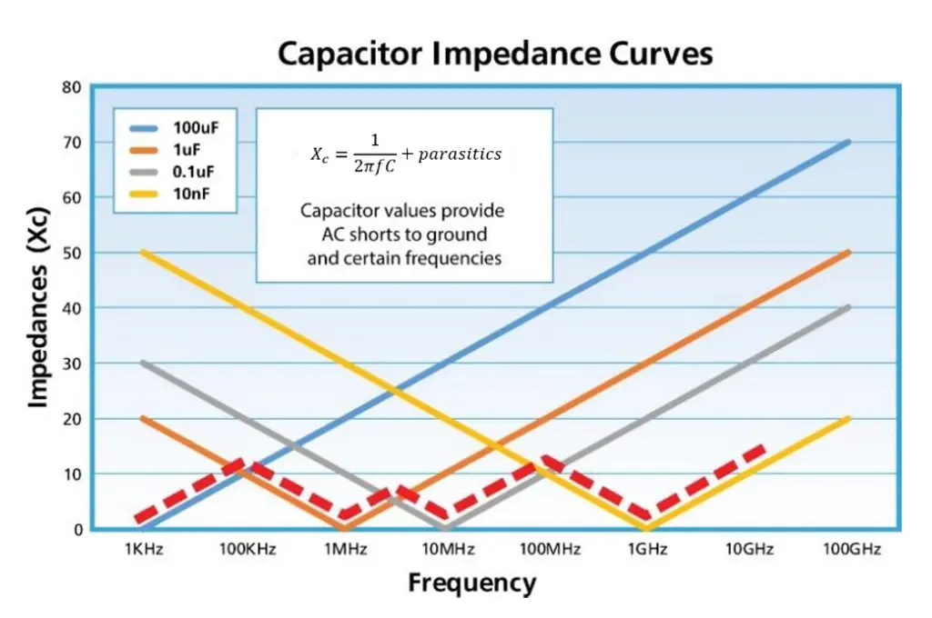
For bypass applications, the paper explains that capacitor values are chosen to provide a low-resistance ground path for unwanted noise signals. It then presents the familiar mathematical expression of capacitor reactance. This equation allows one to determine the theoretical capacitor values needed to provide a low-resistance path to ground for a signal at a given frequency.

In practice, actual capacitors are modeled as a combination of capacitors, inductors, and resistors. A low impedance is realized at a capacitor’s first self-resonant frequency. Above the resonant frequency, the impedance rises as the frequency increases. The paper illustrates this by presenting impedance plots of several capacitors with different values. Furthermore, a common approach to enable broadband RF isolation involves shunting three or four capacitors, each with different values, to ground. Oftentimes, designers employ this method by simply following the recommendations from a manufacturer’s datasheet.

The paper continues by breaking down the parasitic inductance that’s present in a capacitor. It’s noted that increasing a capacitor’s contact pad size can reduce the parasitic inductance. Mention is made of a new manufacturing process that allows for larger pad areas in capacitor footprints without compromising the voltage rating.

Real measurements are shown of the V-Series capacitors, demonstrating how one of them can offer broadband performance that’s typically achieved by bypass networks with multiple capacitors. Additional measurement results compare the performance of a traditional capacitor bypass network with a V-Series capacitor by itself, as well as with a UX-Series capacitor in combination with a V-Series capacitor.

Read more at the technical paper here.

Related

Recent Posts

Researchers Demonstrated High Energy Ceramic Capacitors Stable in Wide Temperature Range

2.10.2025
1

How to Manage Supercapacitors Leakage Current and Self Discharge 

1.10.2025
10

Qualification of Commercial Supercapacitors for Space Applications

1.10.2025
8

Experimental Evaluation of Wear Failures in SMD Inductors

1.10.2025
14

Resonant Capacitors in High-Power Resonant Circuits

1.10.2025
7
a Schematic diagram of the BNT-based components constructed based on the entropy-increase strategy. b Digital photograph, cross-sectional SEM image, and EDS mappings of the MLCCs. c Unipolar P-E loops of MLCCs as a function of applied E. d Wrec and η of the MLCCs as a function of applied E. The comparison of (e) Wrec and η, (f) η and UF of the MLCCs with those of other recently reported state-of-the-art MLCCs. source: Nature Communications

Researchers Proposed Enhanced Energy Storage MLCC

1.10.2025
8

Littelfuse Releases First Reflow-Compatible Illuminated Tactile Switch

1.10.2025
2

Improving SMPS Performance with Thermal Interface Material

30.9.2025
6

Polymer Tantalum Capacitors Beyond AEC-Q200 LEO Satellites

30.9.2025
29

Components Thermal and Frequency Challenges in 6G Base Stations

30.9.2025
10

Upcoming Events

Oct 8
11:00 - 12:00 CEST

PCB Online Shop – simply “Made in Germany” by Würth Elektronik

Oct 14
16:00 - 17:00 CEST

Smart Sensors, Smarter AI: Building Reliable Edge Systems

Oct 17
12:00 - 14:00 EDT

External Visual Inspection per MIL-STD-883 TM 2009

Oct 20
October 20 - October 23

Digital WE Days 2025 – Virtual Conference

Oct 21
October 21 @ 12:00 - October 23 @ 14:15 EDT

Space and Military Standards for Hybrids and RF Microwave Modules

View Calendar

Popular Posts

  • Buck Converter Design and Calculation

    0 shares
    Share 0 Tweet 0
  • Boost Converter Design and Calculation

    0 shares
    Share 0 Tweet 0
  • Flyback Converter Design and Calculation

    0 shares
    Share 0 Tweet 0
  • LLC Resonant Converter Design and Calculation

    0 shares
    Share 0 Tweet 0
  • Dual Active Bridge (DAB) Topology Explained

    0 shares
    Share 0 Tweet 0
  • SEPIC Converter Design and Calculation

    0 shares
    Share 0 Tweet 0
  • What is a Dielectric Constant and DF of Plastic Materials?

    4 shares
    Share 4 Tweet 0
  • Ripple Current and its Effects on the Performance of Capacitors

    3 shares
    Share 3 Tweet 0
  • MLCC and Ceramic Capacitors

    0 shares
    Share 0 Tweet 0
  • Flying Capacitors Explained

    0 shares
    Share 0 Tweet 0

Newsletter Subscription


Passive Components Blog

© EPCI - Leading Passive Components Educational and Information Site

  • Home
  • Privacy Policy
  • EPCI Membership & Advertisement
  • About

No Result
View All Result
  • Home
  • Knowledge Blog
  • Premium Suppliers

© EPCI - Leading Passive Components Educational and Information Site

This website uses cookies. By continuing to use this website you are giving consent to cookies being used. Visit our Privacy and Cookie Policy.
Go to mobile version