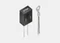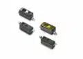
Bourns has introduced the CFG-A Series of wide terminal metal foil current sense resistors, targeting automotive and other high‑reliability applications where accurate current measurement and robust thermal performance are critical.
These AEC‑Q200 compliant wide terminal metal foil current sense resistors extend the existing CFG family with automotive grade models in compact footprints and low milliohm values suitable for modern power electronics designs.
Key features and benefits
- Wide terminal metal foil design for reduced parasitic resistance and improved current distribution across the termination area, helping to maintain measurement accuracy in high‑current paths.
- High power density in compact footprints, with 0508 and 0612 packages supporting up to 2 W depending on value and model, enabling space‑constrained layouts without sacrificing power handling.
- Low resistance range from 1 mΩ to 40 mΩ, tailored for current sensing in power stages where small voltage drops and low conduction losses are important.
- AEC‑Q200 automotive grade qualification, making the series suitable for use in automotive ECUs, on‑board chargers (OBC), inverters and other systems that must meet stringent reliability standards.
- Wide operating temperature range from -55 °C to +155 °C, supporting use in harsh environments and allowing placement close to power devices where board temperature can be elevated.
- RoHS compliant and halogen free construction, supporting corporate environmental and safety requirements without restricting typical automotive and industrial use.
- High reliability and stability under environmental stress, including temperature cycling, humidity and mechanical stress, helping to maintain calibration and long‑term measurement accuracy in demanding service conditions.
Typical applications
The CFG-A Series is intended as a current sense element in a variety of power and control circuits where measurement accuracy, stability and automotive qualification matter.
- Phase current sensing in motor drive inverters for traction, industrial drives and pump/fan control.
- On‑board charger (OBC) current sensing, for monitoring charging current and implementing protection and control loops in EV charging systems.
- General power management systems, including DC link monitoring and output current measurement in converters and power supplies.
- Stepper motor drives and input amplifiers, where a low‑value shunt resistor is used to create a small sense voltage for closed‑loop current control.
- Industrial control systems and other high‑reliability electronics that need stable low‑ohmic shunt resistors with extended temperature capability and rugged mechanical design.
In practice, these resistors are often placed in the source or return path of a power device (for example, MOSFET source shunt) so that the resulting sense voltage can be amplified and digitized for over‑current protection, efficiency optimization, or diagnostics.
Technical highlights
Package options and ratings
The CFG-A Series is released in two wide‑terminal SMD package formats.
| Model | Package | Power rating @ 70 °C | Resistance range | TCR (typical) | Available tolerances |
|---|---|---|---|---|---|
| CFG0508A | 0508 | 1 W | 1 mΩ – 10 mΩ | R < 5 mΩ: ±75 ppm/°C; R ≥ 5 mΩ: ±50 ppm/°C | ±1%, ±5% |
| CFG0612A | 0612 | 1.5 W; 2 W (1–5 mΩ) | 1 mΩ – 40 mΩ | R < 5 mΩ: ±75 ppm/°C; R ≥ 5 mΩ: ±50 ppm/°C; 1–5 mΩ: ±100 ppm/°C at 2 W | ±1%, ±5% |
According to the manufacturer, power ratings are specified at 70 °C and depend on the exact resistance value and mounting conditions, so for detailed derating curves and application‑specific limits the original datasheet should be consulted.
Temperature performance and stability
The specified temperature coefficient of resistance (TCR) reflects the expected change in resistance with temperature and is given in ppm per degree Celsius.
- Values below 5 mΩ typically exhibit TCR around ±75 ppm/°C.
- Values at or above 5 mΩ typically exhibit TCR around ±50 ppm/°C.
- For CFG0612A values from 1 mΩ to 5 mΩ at the highest 2 W rating, TCR is specified at ±100 ppm/°C.
In practical terms, a TCR of ±50 ppm/°C means that over a 100 °C temperature change the resistance changes by up to 0.5%, which is important to consider if the sense current or protection thresholds rely on precise shunt values over wide operating temperatures.
Wide terminal construction and thermal behavior
The wide terminal metal foil construction is specifically chosen to spread heat efficiently into the PCB and reduce localized hot spots on the component.
- Wider terminations distribute current more evenly and reduce the effective lead resistance, contributing to measurement accuracy at high currents.
- Better thermal spreading into the copper allows the device to achieve higher continuous power ratings in compact footprints, assuming appropriate PCB copper and airflow.
Because the resistor temperature is strongly influenced by PCB copper area and thickness, layout decisions (pad size, copper polygons, thermal vias) will have a direct impact on achievable power and measurement stability.
Design‑in notes for engineers
- Check derating against real board temperatures. Power ratings are defined at 70 °C and assume specific PCB conditions; measure or simulate actual resistor temperature in your layout, especially in EV power stages or industrial drives with high ambient and device temperatures.
- Use adequate copper area around pads. The wide terminal format benefits from generous copper to spread heat and reduce temperature rise; small pads or narrow traces will limit the effective power handling and may increase TCR effects in practice.
- Select resistance value based on required sense voltage. Choose milliohm values that yield a measurable voltage at maximum current without excessive dissipation; for example, lower values minimize losses but may demand higher‑gain, low‑offset amplifiers.
- Account for tolerance and TCR in protection thresholds. When designing over‑current or short‑circuit comparators, include resistor tolerance and TCR in worst‑case calculations to avoid nuisance trips or insufficient protection margin.
- Leverage automotive qualification for platform reuse. AEC‑Q200 compliant CFG-A parts can simplify component reuse across multiple vehicle programs and ECUs, reducing qualification effort and supporting global supply strategies.
- Consider mechanical and environmental stress. According to the manufacturer, the series is tested under temperature cycling, humidity exposure and mechanical stress; however, board flex, vibration and thermal shock in the actual application should still be evaluated at system level.
When integrating these resistors in current sensing front‑ends, pay attention to Kelvin connections (separate sense traces from current‑carrying pads) and routing symmetry, to minimize error due to trace resistance or thermal gradients.
Source
This article is based on information provided in the official Bourns new product release for the CFG-A Series wide terminal metal foil current sense resistors and associated technical documentation made available on the manufacturer’s website.