





Magnetic-core selection determines the achievable inductance, saturation margin, power loss, thermal performance and EMI behaviour of inductors and transformers. A useful design process must consider not only nominal permeability and saturation flux density, but also flux waveform, DC premagnetization, temperature, core geometry, air gaps and winding-field distribution.
This article consolidates the fundamentals of magnetic-core materials and permeability with practical loss mechanisms that are often missed when applying simple core-loss models.
Key takeaways
- Magnetic cores increase inductance by concentrating magnetic flux, allowing smaller and more effective inductors and transformers than comparable air-core designs.
- The main soft-magnetic material families are electrical steel, powder cores, ferrites, amorphous alloys and nanocrystalline alloys.
- Permeability is not a fixed material constant in real components; it changes with field strength, frequency, temperature, DC bias, core gap and mechanical stress.
- Core loss includes hysteresis-related, eddy-current and residual dynamic mechanisms; copper loss remains a separate and often equally important part of magnetic-component loss.
- The original Steinmetz equation is a useful first estimate for sinusoidal excitation, but waveform-aware methods and measured loss data are needed for modern switching converters.
- DC premagnetization, relaxation after voltage transitions and orthogonal flux in tape-wound cores can materially increase loss beyond a basic Steinmetz or iGSE estimate.
- Final design release requires prototype validation under worst-case electrical, thermal and mechanical operating conditions.
What a magnetic core does
An inductor consists of one or more windings. Current through the winding creates a magnetizing field H, which establishes magnetic flux density B in and around the component.
Introducing a soft-magnetic core increases the magnetic flux for a given magnetizing force. This increases inductance and enables more compact energy storage, power transfer or common-mode filtering. The trade-off is that real magnetic materials have finite saturation capability and dissipate energy when exposed to alternating flux.
For a winding with N turns around a core with effective cross-sectional area Ae, the voltage applied to the winding is related to the rate of change of flux density:
This relationship is central to power-magnetics design: converter voltage, switching interval, turns count and core area determine the flux excursion. For a constant applied voltage during an interval ton, a first-order estimate is:
The calculated flux swing must be checked against the selected material’s saturation behaviour and loss curves at the relevant temperature.

Magnetic quantities and B–H curves
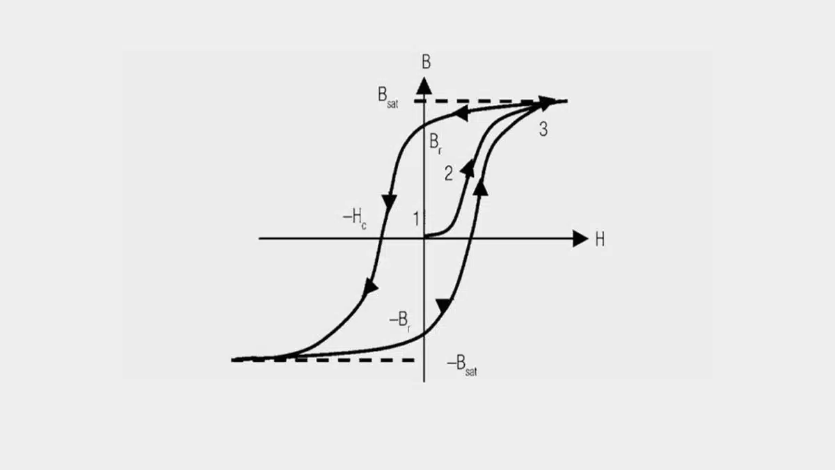
The B–H curve describes how a magnetic material responds to magnetizing force. At low field strength, many soft-magnetic materials show an approximately linear region in which an increase in H produces a large increase in B.
At higher field strength, the material approaches saturation. Beyond this point, a substantial increase in winding current produces only a small increase in flux density, while inductance falls and current can rise rapidly. In switched-mode converters, this can increase current ripple, device stress and thermal load.
When the applied field is reduced, magnetic flux density does not retrace exactly the original path. The enclosed B–H-loop area represents energy dissipated in the core per magnetization cycle.
Important B–H terms include:
- Saturation flux density: The region where further magnetizing force yields only a limited increase in flux density.
- Remanent flux density: The flux density remaining after the applied field returns to zero.
- Coercive field strength: The reverse magnetic field required to reduce remanent flux density to zero.
- Initial permeability: The low-signal permeability measured near the origin of the B–H curve.
- Incremental permeability: The local slope around a defined DC operating point, especially relevant in biased inductors.
For storage inductors, designers normally ensure that the combined DC flux and AC excursion remain outside the strongly saturating region over the full temperature, tolerance and transient envelope. For ferrite beads and some EMI components, by contrast, a substantial resistive loss contribution may be intentional because it converts unwanted high-frequency energy into heat.
Core material families
Core material is selected according to the function of the magnetic component: power transfer, energy storage, current sensing, common-mode filtering or broadband EMI suppression. No single material family is universally best.
| Material family | Main strengths | Typical limitations | Common applications |
|---|---|---|---|
| Electrical steel and silicon steel laminations | High saturation flux density, cost-effective at low frequency | Eddy-current loss limits high-frequency use; requires laminations | Mains transformers, line reactors, motors, grid-frequency magnetics |
| Iron powder cores | Distributed air gap, useful DC-bias capability, robust saturation behaviour | Higher loss than ferrites in many high-frequency designs | PFC inductors, output chokes, RF and power inductors |
| Advanced powder cores | Improved loss, temperature stability or bias performance versus basic iron powder | Material-specific cost and availability; loss behaviour must be checked by grade | High-current storage inductors, PFC, industrial and automotive power magnetics |
| MnZn ferrites | High permeability and low eddy-current loss for mainstream power magnetics | Lower saturation flux density than metals; properties change with temperature and bias | SMPS transformers, resonant inductors, flyback and forward magnetics |
| NiZn ferrites | High resistivity and useful high-frequency impedance behaviour | Lower permeability than MnZn grades | Ferrite beads, cable suppressors, common-mode filters and RF EMI control |
| Amorphous ribbon cores | High saturation flux density and low loss in suitable frequency ranges | Tape construction requires careful treatment of gaps and leakage fields | High-power transformers, current sensing, specialised power magnetics |
| Nanocrystalline ribbon cores | Very high permeability, high performance in sensing and EMI applications | Gap fringing, transverse flux and mechanical handling can be critical | Current transformers, common-mode chokes, precision sensing, high-performance transformers |
Electrical steel and laminated cores
Electrical steel and silicon steel remain important where frequency is low and high saturation capability is valuable. Laminating the material interrupts eddy-current paths; lamination thickness, coating quality and stacking method strongly influence loss.
These cores are common in mains-frequency transformers, line reactors and rotating machines. They are generally not the preferred choice for high-frequency switched-mode magnetics unless specialised thin-gauge material and carefully controlled conditions are used.
Powder cores and distributed gaps
Powder cores consist of electrically insulated magnetic particles held in a binder matrix. The particle insulation raises electrical resistance and creates a distributed magnetic gap throughout the material.
This distributed-gap structure gives a comparatively gradual reduction of inductance with DC current, which is valuable in energy-storage inductors. Iron powder, sendust or FeSiAl-type materials, High-Flux-type materials and MPP-type materials each represent different compromises among permeability, DC-bias capability, core loss, temperature behaviour and cost.
A powder core is not automatically a low-loss solution. Its loss density must be evaluated using the actual material grade, switching frequency, flux swing, temperature and waveform.
Ferrites: MnZn and NiZn
Ferrites are ceramic magnetic materials formed from iron oxide combined with other metal oxides, then pressed and sintered into the required geometry. Their high resistivity strongly limits classical eddy-current loss, making them highly suitable for high-frequency power conversion and EMI suppression.
MnZn ferrites are widely used in power transformers, resonant magnetics and inductors. Their high permeability makes them useful for compact designs, but their saturation margin, AC loss and DC-bias response must be checked over temperature.
NiZn ferrites generally have lower permeability and higher resistivity than MnZn materials. They are commonly used where impedance and loss at higher frequencies are needed, including ferrite beads, cable suppressors and EMI filters.
The usable frequency range cannot be determined from material family alone. Designers should use the manufacturer’s loss curves, permeability curves and impedance data for the exact material grade and component geometry.
Amorphous and nanocrystalline ribbon cores
Amorphous and nanocrystalline soft-magnetic materials are commonly produced as thin rapidly solidified ribbons that are wound into toroidal, C-core or cut-core shapes. Their thin ribbon structure limits eddy-current loss when the main magnetic flux follows the intended direction through the laminated structure.
Amorphous alloys can provide high saturation flux density and attractive loss performance in selected applications. Nanocrystalline alloys offer very high permeability and are widely used in current sensing, common-mode filtering and specialised high-performance magnetics.
These materials require particular care where a discrete air gap, high leakage flux or mechanical cutting is involved. Flux components transverse to the ribbon plane can enable extensive eddy-current loops and substantially increase loss.

Core shapes, gaps and fringing fields
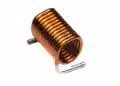
Core geometry affects inductance, winding area, thermal path, leakage inductance, electromagnetic shielding and manufacturability. Common shapes include rods, toroids, E-cores, U-cores, pot cores, planar cores, multi-aperture cores and ferrite beads.
A discrete air gap is often introduced into a ferrite core to store energy and prevent abrupt saturation in DC-biased inductors. If the air gap dominates the magnetic reluctance, a first-order approximation is:
where lg is the effective air-gap length. This is a simplified relation; fringing flux, finite core permeability and distributed-gap effects must be included for final design calculations.
Air gaps produce fringing fields. These fields can cause additional AC copper loss in nearby winding turns through proximity effect and can heat conductive shields, clips or PCB copper. In tape-wound amorphous and nanocrystalline cores, gap fringing can also introduce transverse flux through the ribbons and raise core loss.
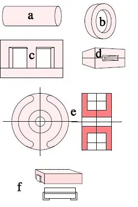
· a) cylindrical rod core
· b) toroid or “attenuation bead”
· c) E core with yoke
· d) attenuation ferrite for flat conductor cable
· e) pot core
· f) SMD ferrite.
Permeability and operating point
Permeability describes how readily a material supports magnetic flux. Relative permeability is defined as:
where is the permeability of free space. In a simplified linear region:
In practice, relative permeability is not constant. It depends on several variables:
- Magnetic field strength and AC flux excursion
- DC premagnetization and local operating point on the B–H curve
- Frequency and waveform
- Core temperature
- Mechanical stress, assembly force and potting stress
- Air-gap length, distributed-gap structure and geometry
- Material composition and manufacturing process
High permeability can enable high inductance with fewer turns, but it does not automatically mean that a material is appropriate for high DC bias or low loss. A discrete or distributed air gap is frequently used to lower effective permeability and increase energy-storage capability.
For a detailed explanation of saturation-current behaviour in practical components, see Inductor Saturation Current Explained.
Complex permeability and EMI behaviour
At higher frequencies, permeability is represented as a complex quantity:
The real component represents the energy-storage behaviour associated with inductance. The imaginary component represents magnetic loss.
This distinction explains why a magnetic component may act as an inductor at one frequency and as a lossy EMI suppressor at another. In a ferrite bead, the resistive impedance contribution at the interference frequency is often more useful than a high inductive reactance because it damps resonances and dissipates unwanted RF energy.
The magnetic loss tangent can be expressed as:
A higher loss tangent indicates a larger resistive contribution relative to the inductive contribution. Impedance plots from the actual component manufacturer are therefore essential when selecting ferrite beads or common-mode filtering elements.
Where core losses come from
Core loss is the energy dissipated within the magnetic material. It should be distinguished from winding loss, termination loss and eddy-current loss in adjacent conductive structures.
| Loss contribution | Physical origin | Key design variables |
|---|---|---|
| Hysteresis or static loss | Irreversible magnetic-domain processes and B–H-loop area | Material grade, flux density, temperature, DC operating point |
| Classical eddy-current loss | Induced circulating currents in electrically conductive material | Material resistivity, ribbon or lamination thickness, frequency, geometry |
| Residual or excess loss | Dynamic domain-wall motion and other material-dependent mechanisms | Material grade, frequency, flux waveform and empirical measurement data |
| Winding DC loss | Resistive loss from conductor resistance | Copper cross-section, turns count, temperature |
| Winding AC loss | Skin effect, proximity effect and fringing-field exposure | Frequency, conductor geometry, winding arrangement and gap placement |
The total dissipation of an inductor or transformer is the combination of core and copper losses. Reducing core loss by adding turns may increase winding resistance and copper loss; reducing turns may lower copper loss but raise flux swing and core loss. The optimum is therefore a system-level thermal and efficiency trade-off.
Core-loss estimation methods
The original Steinmetz equation is widely used as a first estimate of core-loss density:
Here, is volumetric core-loss density, f is excitation frequency, is the flux-density excursion, and k, and are material-specific fitted coefficients.
The original Steinmetz equation is normally derived from sinusoidal measurement data. It must therefore not be treated as a universal model for rectangular, triangular, asymmetric, discontinuous or strongly DC-biased converter waveforms.
For switched-mode power supplies, a waveform-aware method such as the improved generalized Steinmetz equation can provide a better approximation because it evaluates the rate of flux change, , over individual waveform segments. This is particularly relevant for flyback, forward, buck, boost, PFC, phase-shifted and resonant topologies.
Use the following hierarchy for practical design work:
- Use manufacturer loss curves measured near the intended temperature, frequency and flux-density range whenever available.
- Use Steinmetz coefficients only within the operating range used to derive them.
- Apply waveform-aware modelling for non-sinusoidal excitation.
- Assess DC bias separately if the chosen model or manufacturer data does not include it.
- Validate total loss and temperature rise on representative hardware.
Core-loss effects often missed
DC premagnetization
A DC current component shifts the operating point along the B–H characteristic. The core then follows minor loops around this biased operating point rather than operating symmetrically around zero field.
This is important in buck and boost inductors, PFC chokes, current-sensing elements and power-transformer applications with asymmetric drive. The same AC flux excursion can produce higher loss when DC premagnetization is present.
The magnitude of this effect depends on material and operating point. It has been observed in ferrites, electrical steels and nanocrystalline materials, while some powder-core materials may show a smaller response. Designers should use bias-dependent loss data where available or measure the material under the intended DC and AC conditions.
Relaxation after voltage transitions
Some power-electronics waveforms contain voltage plateaus or periods of nearly constant flux. Examples can occur in dual-active-bridge converters, phase-shifted topologies, burst operation and asymmetric modulation schemes.
A simple waveform-loss calculation may assume that no additional magnetic loss occurs while flux remains constant. In real materials, magnetic relaxation can continue after a rapid voltage transition as the material approaches a new internal equilibrium.
The practical consequence is that energy dissipated per cycle can increase during a nominally constant-flux interval. This effect is most relevant when long dwell periods, strongly asymmetric duty cycles or repeated abrupt changes in occur.
Orthogonal flux in tape-wound cores
Amorphous and nanocrystalline ribbon cores are designed for magnetic flux that follows the intended path along the wound ribbons. Their thin insulated ribbon construction suppresses eddy currents for this main flux direction.
A discrete air gap can produce fringing flux transverse to the ribbons. Leakage flux in a transformer window can have a similar effect. This transverse field can drive large in-plane eddy-current loops within the ribbons, creating a loss contribution that is not obvious from conventional one-dimensional core-loss modelling.
For tape-wound cores, avoid large discrete gaps where possible, minimise leakage fields, consider distributed-gap alternatives where appropriate, and keep windings and gap geometry under tight control. Core cutting and edge treatment also matter because poor processing can create unwanted electrical connections between ribbons.
Mechanical and thermal stress
Mechanical clamping, encapsulation, thermal cycling and assembly stress can alter magnetic behaviour and loss. The magnitude is material- and construction-dependent, so it should not be assumed from a generic value.
For high-permeability materials, tight thermal margins or precision current-sensing applications, validate the finished magnetic assembly rather than only a loose core sample.
Application fit
Core family selection should begin with the function of the magnetic component, not with a nominal permeability value alone.
| Application | Suitable starting material families | Primary selection checks |
|---|---|---|
| Mains transformer or line reactor | Electrical steel laminations | Frequency, lamination loss, temperature rise, insulation system |
| PFC inductor or high-current boost choke | Iron powder, advanced powder core, gapped ferrite | DC bias, peak current, loss density, fringing-field copper loss |
| Flyback or forward transformer | MnZn ferrite | Flux swing, core loss at temperature, insulation and leakage inductance |
| LLC transformer or resonant inductor | Low-loss MnZn ferrite; specialised ribbon materials where justified | Loss across frequency range, magnetising current, leakage inductance and thermal margin |
| Buck or multiphase output inductor | Powder core or gapped ferrite | DC bias, inductance roll-off, AC loss and saturation margin |
| Current-sense transformer | Ferrite or nanocrystalline core | Accuracy, permeability stability, saturation, bandwidth and insulation |
| Common-mode choke | Ferrite or nanocrystalline core | Common-mode impedance, DC-current tolerance, parasitic capacitance and thermal behaviour |
| Ferrite bead or cable suppressor | NiZn ferrite and application-specific ferrite materials | Impedance-versus-frequency curve, DC bias, current rating and self-heating |
This table is a first-pass guide only. Final selection must be based on the exact material grade, core shape, air-gap arrangement, winding design, operating waveform and qualification requirements.
Design-in notes for engineers
- Start with the waveform. Derive the actual voltage across the winding, switching intervals, DC offset, peak current and flux excursion before selecting material.
- Use temperature-dependent data. Core loss can change significantly with temperature, and the material’s loss minimum may not occur at room temperature.
- Separate core and copper loss. A low core-loss design may require more turns, which can increase DC resistance and AC winding loss.
- Check DC bias explicitly. Do not assume that a zero-bias ferrite loss curve represents a heavily biased storage inductor.
- Treat gaps as field sources. Place sensitive winding turns away from discrete gaps where possible and consider shielding or alternative geometry only after checking the associated eddy-current impact.
- Be cautious with ribbon cores. In amorphous and nanocrystalline constructions, assess gap fringing and leakage flux for transverse-field loss.
- Use the correct measurement conditions. Loss data are meaningful only when frequency, flux swing, waveform, temperature, bias and sample geometry are sufficiently comparable to the application.
- Validate the finished assembly. Measure efficiency, winding temperature, core temperature and current waveform at worst-case input voltage, load, frequency and cooling condition.
- Allow design margin. Material tolerances, core-gap tolerances, DC offset, startup behaviour and elevated ambient temperature can all reduce saturation margin.
For practical converter calculations, see Buck Converter Design and Calculation and Flyback Converter Design and Calculation.
Conclusion
Magnetic-core selection is no longer a simple choice between permeability and saturation flux density. In practical power-magnetics design, the final result depends on the interaction of material family, flux waveform, DC bias, frequency, temperature, gap geometry, winding layout and thermal constraints.
Ferrites, powder cores, electrical steels, amorphous alloys and nanocrystalline alloys each offer useful operating windows rather than universal superiority. The most reliable workflow is to start from the required electrical function, derive the real flux excursion from the applied waveform, check core and copper losses separately, and then validate the finished assembly under worst-case operating conditions.
For modern converters, especially those with non-sinusoidal excitation, strong DC premagnetization or high leakage and fringing fields, measured application-specific data remain more trustworthy than any simplified loss equation used in isolation.
FAQ: Magnetic core materials, permeability and losses
A magnetic core concentrates magnetic flux generated by the winding, which increases inductance and allows a smaller component than an equivalent air-core design. The trade-off is that the core introduces saturation limits and frequency-dependent losses.
The main soft-magnetic families used in passive components and power magnetics are electrical steel laminations, iron powder and other powder cores, MnZn ferrites, NiZn ferrites, amorphous ribbon cores and nanocrystalline ribbon cores. Each family is suited to different combinations of frequency, DC bias, loss target and application function.
Higher effective permeability generally increases inductance for a given turns count and geometry. In practice, however, permeability changes with frequency, field strength, DC operating point, temperature, air gap and material construction, so it must not be treated as a fixed value.
Core loss is usually discussed as a combination of hysteresis-related loss, eddy-current loss and residual or excess dynamic loss. In a finished magnetic component, these losses must still be evaluated separately from copper DC and AC winding losses.
The original Steinmetz equation is a useful first estimate, but it is typically fitted to sinusoidal test data. Real converter waveforms are often rectangular, asymmetric, DC-biased or segmented, so waveform-aware modelling and measured material data are usually needed for better accuracy.
DC premagnetization shifts the operating point on the B–H curve and changes the minor hysteresis loops traced by the material. As a result, the same AC flux swing can produce different loss under DC bias than under zero-bias conditions.
An air gap helps prevent abrupt saturation and supports energy storage, but it also creates fringing flux. That fringing field can increase AC copper loss in nearby windings and, in tape-wound amorphous or nanocrystalline cores, may also increase core loss through transverse flux.
Ferrites are a common first choice for high-frequency transformers and many inductors, powder cores are often preferred for DC-biased energy-storage applications, and amorphous or nanocrystalline ribbon cores are especially attractive in sensing, common-mode filtering and selected high-performance power designs. Final selection depends on the exact waveform, loss target, thermal budget and mechanical implementation.
Start from the actual converter function and waveform, estimate flux swing and DC bias, compare candidate materials using loss and permeability data for the real operating range, then confirm performance and temperature rise on prototype hardware.
How to select a magnetic core material for an inductor
- Define the inductor function and topology
Determine whether the magnetic part is intended for energy storage, power transfer, current sensing, common-mode filtering or broadband EMI suppression, because this strongly narrows the suitable material families.
- Derive the actual electrical operating conditions
Identify switching frequency, duty cycle, voltage across the winding, DC current, ripple current, transient conditions and any low-frequency modulation or burst behaviour.
- Estimate flux swing and saturation margin
Use turns count, effective core area and applied voltage-time product to estimate flux excursion, then confirm that the material remains outside the strongly saturating region across tolerance and temperature limits.
- Choose candidate material families
Use ferrite, powder-core, electrical-steel, amorphous or nanocrystalline options according to the required frequency range, DC-bias tolerance, loss target, size and application type.
- Check permeability under real operating conditions
Review effective permeability, incremental permeability, bias dependence, temperature behaviour and any influence of air gaps or distributed-gap construction.
- Estimate core loss using appropriate data
Use manufacturer loss curves where possible, then apply Steinmetz-based or waveform-aware methods only within their valid operating range and assumptions.
- Assess secondary field effects
Check for fringing flux, winding AC loss, leakage-field effects, shielding interactions and any transverse-field risk in tape-wound ribbon materials.
- Build and measure a prototype
Validate efficiency, waveforms, saturation margin and temperature rise under worst-case voltage, current, cooling and ambient-temperature conditions.
- Add design margin before release
Allow margin for material tolerance, gap variation, thermal drift, startup conditions, overload events and production spread before freezing the design.
Further reading
- Inductor and Choke, What is it ?
- Why Power Inductors Use a Ferrite Core With an Air Gap
- Inductance, Impedance, Q Factor and DCR Losses
- Current Sense Transformers: Ferrite vs Nanocrystalline Cores for Accurate Current Measurement
Source
This updated knowledge article consolidates the existing Passive Components Blog material with the linked Frenetic educational webinar on magnetic-core losses. Engineers should consult current manufacturer datasheets, material-characterisation data and component documentation for final selection, qualification and design release.