








This article by Dr. V. Azbel, an Independent consultant on tantalum capacitors, discusses methodology for evaluating the stability of tantalum capacitor anodes after testing based on mechanical testing.
Tantalum capacitors (TCs) are considered among the most reliable types of capacitors, especially in critically important fields such as the military and aerospace industries and medicine. A key factor in their reliability is the stability of leakage currents (DC leakage, DCL) during operation.
The anode plays the primary role in ensuring DCL stability. Changes in DCL during operation or testing indicate structural changes in the anode. The overall reliability of TCs depends on how critical these changes are for maintaining the anode’s stability. A mechanical method was applied to analyze the structure of the anode. Unlike previous studies focused on the influence of technological factors on the main parameters of the anode (porosity, formation, sintering regimes, etc.) /3 /, this article emphasizes the impact of TC testing conditions while keeping the main parameters of the anode unchanged.
The analysis uses an anode model / 1/ that accounts for the stress gradient variations within its structure. Changes are explained using the composite yield strength equation derived from compression tests, accompanied by stress-strain curve recordings.
The study aimed to assess changes in the structure of TC anodes (see Table 1a) that underwent leakage current tests under different conditions (see Table 1b) compared to reference samples. Additionally, the study examined how these changes affect TC reliability and what causes them. The results of the research can help adjust the manufacturing process of anodes if necessary to improve their reliability under real operating conditions.
The TCs and their tests were provided by NASA.

- Air,3000h,75°C -5V
- Vacuum.,3000h./75°C -5V
- Vacuum.,2500h./85°C -5V
- 22C 7%RH -5V
- 20C 85%RH -5V
Fig. 1b Condition testing
For the study, anodes obtained by stripping from TCs of the 293D, 194D, and CWR06 series were used. These anodes underwent leakage current tests over time according to the regimes shown in Fig. 1b. Figure 2 presents graphs of leakage current versus time for TCs (see Fig. 1a) under various testing conditions (see Fig. 1b).

The influence of testing conditions is illustrated by comparing the theoretical graph of an ideal anode (see Fig. 2a) with experimental data (see Figs. 2b–f). As shown in Fig. 2b, the behavior of DCL at a temperature of 125°C is close to the ideal case. However, the simultaneous effects of temperature (see Figs. 2e, 2f), reverse voltage (see Figs. 2e, 2d), and humidity significantly impact the DCL behavior compared to the ideal anode (see Fig. 2a).
The behavior of DCL over time can be considered an indicator of the aging process of the anode, caused by changes in its structure. Differences in DCL behavior reflect the influence of various degradation mechanisms in the anode structure, which can be monitored using mechanical properties: yield strength, plasticity, and elastic modulus, as determined from the stress-strain curve following the methodology described in [source].
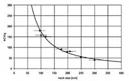
Before mechanical testing, the anodes were characterized by their dimensions, weight, and film color (see Fig. 3). The forming voltage was estimated with an accuracy of ±5 V based on the film color, allowing for the determination of the CV/g value of the anode and the CV/g value of the powder used for the production of each design, as well as the neck sizes (see appendix Fig. A).

Main Results
The anodes were subjected to mechanical testing using the methodology described in [source], which allowed the determination of their yield strength and plasticity (see Fig. 4a). The graph shows the changes in yield strength (ΔA – bars) and plasticity (Δpl – triangles) of the anodes under various testing conditions, expressed as percentages relative to the reference value.

As shown in the graph (Fig. 4a), the most significant changes in yield strength are observed during vacuum testing, particularly with increased temperature (from 75°C to 85°C). The CWR06 series exhibits minimal changes in yield strength, indicating their high stability compared to the 293D and 194D series.
The plasticity of the anodes significantly decreases under the influence of air and elevated temperatures in a vacuum. The reduction in ductility is most pronounced for the 194D anodes, indicating their lower resistance to changing conditions.
Exposure to moisture leads to embrittlement of all anodes, as illustrated by a typical stress-strain diagram for all tested anodes (see Fig. 4c). These changes in yield strength, compared to the reference values, highlight the impact of testing conditions on the structural changes in the anodes. According to the model in [1], an anode is a composite material consisting of a tantalum neck, an amorphous Ta₂O₅ film, and an interfacial zone separating them. This zone represents a modified surface layer of the tantalum neck with a nanocrystalline structure.
Let us consider how testing conditions affect each structural component of the anode, using the yield strength as an indicator. To explain the yield strength behavior of the anode, the equation for the yield strength of a composite material was applied:
Ac= V1*A1 + V2*A2 + V3*A3 (1)
where:
- V1, V2, V3— volume fractions of the composite components, for the anode 1—Ta neck, 2—interface zone, 3—amorphous Ta2O5 film,
- A1 , A2, A3 — yield strength of the corresponding components
Yield Strength
Yield strength is the stress at which mass dislocation movement begins in the crystalline lattice of a material, causing irreversible plastic deformation.
For component 3 (the amorphous Ta₂O₅ film) in Equation 1, the parameter V3 lacks physical meaning for this phase. Its contribution to the yield strength V3 is usually considered zero. Thus, Equation 1 takes the following form:
Ac= V1*A1 + V2*A2 ( 2 )
Structural Characteristics of Composite Components and Their Influence on Mechanical Properties
Equation (2) leaves two key parameters that influence the yield strength of the anode: the yield strength of the tantalum neck (V1*A1 .) and the nanocrystalline structure (V2*A2 ). let’s take a look at what represents the structure of the tantalum neck and the interface zone, and how their contributions affect Ac.
Tantalum Neck:
Its small size and formation technology closely resemble the creation of a monocrystalline state. In a monocrystalline volume, dislocation mobility remains high and yield strength low. The main factors affecting A1 are internal defects such as vacancies and inclusions.
Interface Zone:
As described earlier, this represents a modified surface layer of the tantalum neck with a nanocrystalline structure of the same phase composition as the tantalum neck. Such a structure, according to the relationship between yield strength and grain size / /, exhibits abnormally high yield strength and low ductility.
From the above, it can be concluded that two different mechanisms are responsible for the yield strength and plasticity of such a composite material. The interface zone, with its nanocrystalline structure, determines its yield strength, while the tantalum neck governs its ductility.
Testing conditions do not directly affect the volume fractions V1, V2, V3, or the parameters A1 and A2; however, secondary effects such as the degradation of the amorphous Ta₂O₅ structure may influence them.
Mechanism of Yield Strength Changes
Effect of Temperature and Reverse Stress:
The effects of temperature and reverse voltage, despite differences in mechanisms, lead to dipole reorientation and the weakening of the Ta–O bond in ATO. The presence of stress gradients between structures causes the diffusion of oxygen and oxygen vacancies from ATO into the interface zone.
The nanocrystalline structure of the interface zone, its formation technology, and its position between phases with different thermal expansion coefficients create compressive stresses located in the near-surface regions of the tantalum neck. Oxygen diffusion from ATO into the interface zone transforms part of these compressive stresses into tensile stresses.
This results in an increase in the yield strength Ac, while tensile stresses exert pressure on the volume of the tantalum neck, reducing dislocation mobility and ductility.
Effect of Atmosphere
Vacuum:
In a vacuum, the only source of oxygen is the oxygen bound to tantalum in ATO. Under the influence of temperature and reverse stress, the Ta–O bond weakens, resulting in unbound oxygen, which can diffuse into the interface zone. This affects Ac. The magnitude of yield strength changes depends on the amount of unbound oxygen formed in ATO, which in turn is determined by the testing conditions. This can serve as an indicator of the suitability of testing conditions.
Air:
In air, where free oxygen is available, the balance of stress gradients is maintained. Free oxygen replaces the oxygen that diffuses from ATO into the interface zone and the Ta matrix, leading to reduced dislocation mobility (ductility) and having less impact on yield strength changes compared to a vacuum.
Moisture:
In the presence of moisture and reverse stress, water electrolysis occurs, producing hydrogen. The high diffusivity of hydrogen enables its penetration into the Ta matrix, causing embrittlement of the matrix and a loss of ductility.
Conclusions
- The mechanism of yield strength changes in the anode begins with the degradation of amorphous Ta₂O₅, leading to the diffusion of oxygen vacancies and oxygen atoms into the interface zone.
- The critical role of the interface zone in ensuring the stability and low aging risk of anodes has been demonstrated.
- The primary factor influencing yield strength changes is the degradation of amorphous Ta₂O₅ under varying testing conditions.
- The most significant yield strength changes are observed in a vacuum at elevated temperatures (75–85°C).
- Moisture combined with reverse voltage causes brittle failure of the anode.
- Differences in yield strength before and after testing (>10% /2 /) can serve as an indicator of TC failure risks.
- Controlling the state of the interface zone is a key factor in preventing anode degradation in TCs. This is achieved by optimizing the structure of the sintered pellet, forming stress, and process rates.
Appendix
References
- V. Azbel Optimize Tantalum Capacitor Performance by Anode Modeling 12.2024
- Tantalum Capacitors Reliability, Leakage Current Stability Prediction and Cost Reduction by Anode Characterization During Manufacturing Process; Vladimir Azbel; consultant; Israel
- Blog V. Azbel https://passive-components.eu/tag/azbel/