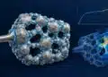






Tantalum and niobium capacitors are polarised electrolytic capacitor that provide high capacitance in compact packages with relatively stable capacitance under DC bias.
This guide explains their construction, electrical characteristics, failure mechanisms and application limits, helping design and component engineers select between MnO2 tantalum, conductive-polymer tantalum, niobium oxide and wet tantalum technologies.
Key Takeaways
- Solid tantalum capacitors use a porous tantalum anode and a Ta2O5 dielectric. Their cathode system contains either manganese dioxide or a conductive polymer; wet tantalum capacitors use a liquid electrolyte and a separate cathode structure.
- Conductive-polymer tantalum capacitors generally offer lower equivalent series resistance, better high-frequency capacitance retention and reduced ignition risk compared with MnO2 types. High-reliability polymer products are available, but qualification and screening apply to specific series and ordering options.
- Voltage selection must account for DC bias, ripple peaks, transients, operating temperature and application derating. Rated voltage, temperature-dependent category voltage and surge-voltage test ratings are not interchangeable.
- Niobium oxide capacitors use a conductive NbO anode, an Nb2O5 dielectric and an MnO2 cathode system. Their additional self-arresting mechanism reduces the likelihood of a low-resistance breakdown, but does not eliminate the need for fault protection.
- Wet tantalum capacitors are useful where low leakage, compact energy storage and environmental robustness justify their cost and construction. Cathode design strongly influences capacitance, ESR and reverse-transient capability.
- Select the exact part number using guaranteed capacitance, ESR, leakage, ripple-current and temperature limits. Check polarity, assembly conditions, moisture sensitivity, qualification, lifecycle status and the consequences of a capacitor short circuit.
Positioning Tantalum and Niobium Capacitors Among Other Capacitor Types
Tantalum and niobium capacitors occupy the space between small ceramic capacitors and larger bulk electrolytic solutions. Their value is not determined by nominal capacitance alone: usable capacitance, leakage, ESR, ripple-current capability, voltage margin, package volume and required reliability must be evaluated together. [1, 2]
Compared with liquid-electrolyte aluminium capacitors, solid tantalum capacitors avoid electrolyte dry-out and generally provide stable capacitance over storage and operation within their specified conditions. This does not mean that all tantalum capacitors have unlimited service or storage life. Conductive-polymer properties, encapsulation, terminations and solderability can change with environmental exposure, while wet tantalum capacitors depend on the integrity of their electrolyte containment. [1, 2, 6]
Compared with Class II multilayer ceramic capacitors, tantalum devices generally retain capacitance more consistently with DC bias and do not exhibit the same ferroelectric piezoelectric behaviour. MLCCs may nevertheless provide lower impedance at high frequencies and a more economical solution at suitable capacitance and voltage values. Compare effective capacitance under the intended conditions rather than comparing nameplate values alone. [2]
Aluminium electrolytic and aluminium-polymer capacitors remain important alternatives for bulk capacitance and ripple-current handling. Film capacitors and other technologies may be more appropriate where non-polar operation, high voltage, very low leakage or pulse duty dominates the requirement. No single capacitor family is preferable across all these conditions.
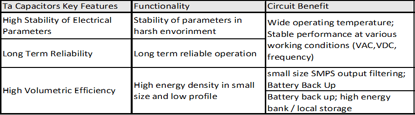
The principal constructions discussed in this article are:
- Solid tantalum electrolytic capacitors with an MnO2 cathode system.
- Solid tantalum electrolytic capacitors with a conductive-polymer cathode system.
- Niobium-metal and niobium oxide capacitors with an Nb2O5 dielectric and an MnO2 cathode system.
- Wet tantalum electrolytic capacitors with a liquid electrolyte and a cathode structure within the case.
Available capacitance and voltage combinations differ substantially between these families. The highest capacitance and highest voltage in a catalogue are not generally available together in the same package. Apply the same caution to published minimum ESR values and maximum ripple-current ratings. [1, 2, 4, 6]
Fundamentals and Volumetric Capacitance
The high capacitance density of tantalum capacitors comes from a large internal electrode area separated from the cathode by a thin oxide dielectric. Capacitance density, charge density and energy density describe different properties and should not be used interchangeably. [3, 6]
In the idealised parallel-plate relationship, C is capacitance in farads, ε0 is the permittivity of free space, εr is the relative permittivity of the dielectric, A is the effective electrode area in square metres and d is dielectric thickness in metres. Eq. (1) describes the main design relationships, although a porous capacitor requires a distributed electrical model to describe its frequency response.
The relative permittivity belongs to Ta2O5, not to the conducting tantalum metal. A representative value is approximately 26, compared with about 8.4 for aluminium oxide. These material values help explain the technology, but electrode area, dielectric thickness, pore accessibility and packaging also determine the capacitance of a finished component. [6]
Charge Q, measured in coulombs, equals capacitance multiplied by applied voltage V. Charge density qVol additionally requires division by the defined volume Vold, as shown in Eq. (2). State whether Vold is the active anode volume, component body volume or installed board volume when comparing designs.
Stored energy W, measured in joules, depends on the square of voltage. Eq. (3) defines energy density wVol for a capacitor whose capacitance can be treated as constant over the voltage range. Use the actual operating voltage rather than rated voltage when calculating energy available to the application.
High capacitance density does not automatically imply high power capability. ESR produces heat during charge and discharge, while internal and mounting inductance limit fast current delivery. For hold-up applications, the useful energy also depends on the lowest voltage at which the downstream circuit can continue operating. [1, 2]
Construction and Manufacturing Process
Tantalum capacitors are manufactured from capacitor-grade tantalum powder; niobium-metal and niobium oxide capacitors use the corresponding niobium-based anode materials. These technologies share the principle of forming a dielectric oxide on a porous anode, but their materials, process conditions and finished electrical limits are not identical. [1, 5]
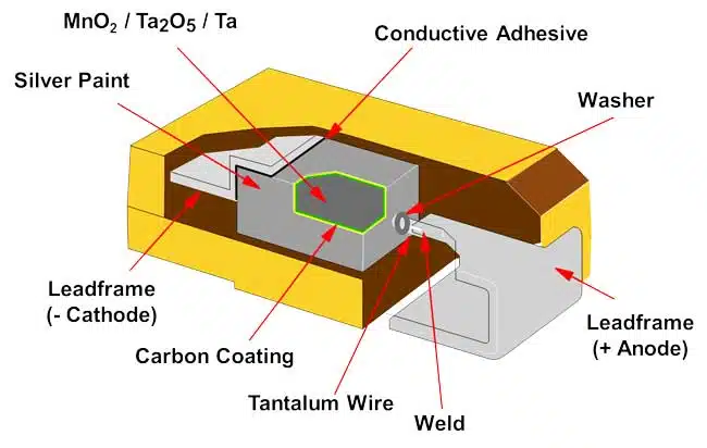
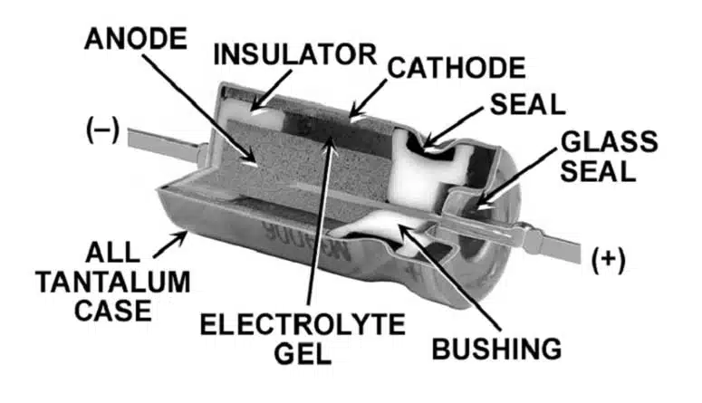
Pressing and Sintering
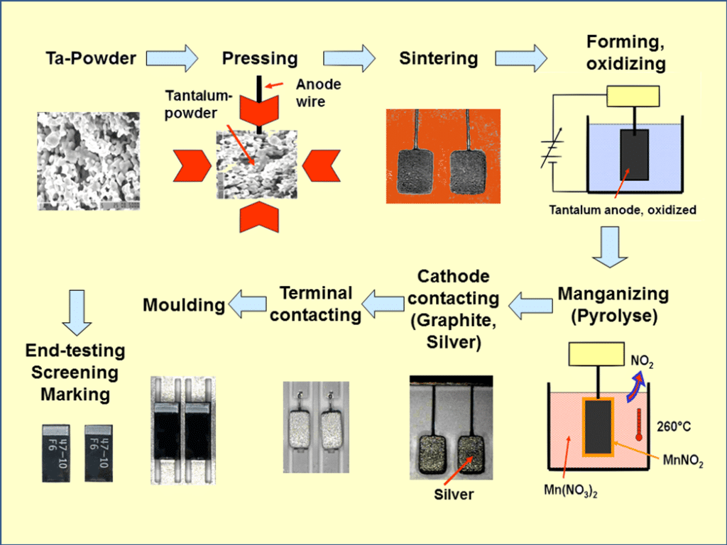
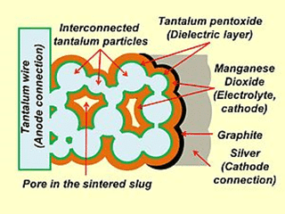
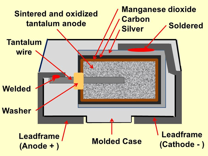
For a conventional tantalum anode, powder is pressed around a tantalum riser wire to form a pellet. The riser wire provides the positive electrical connection. Vacuum sintering joins the particles into a mechanically coherent, electrically continuous porous structure while preserving the internal area needed for capacitance. [3]
Powder morphology, pressing density and sintering conditions balance surface area, mechanical strength, pore accessibility and dielectric quality. Finer powders can increase available area, but narrow or poorly connected pores make subsequent dielectric formation and cathode coverage more demanding. A powder specification therefore cannot be translated directly into finished-component capacitance density.
Dielectric Formation
The porous anode is immersed in a forming electrolyte and anodised. A controlled electrical process grows Ta2O5 over the accessible tantalum surfaces. The formation voltage VF largely determines oxide thickness, while the finished capacitor receives a lower rated voltage VR appropriate to its construction and reliability requirements. [1, 3]
Eq. (4) expresses the approximate relationship between dielectric thickness d and formation voltage. The growth coefficient kF depends on the material and formation conditions. The KYOCERA AVX application guide uses approximately 1.7 nm/V for tantalum pentoxide; this is a process approximation, not a finished-component tolerance. [1]
Using that coefficient, formation at 10 V gives an approximate thickness of 17 nm, while formation at 200 V gives approximately 340 nm. These values illustrate the relationship only; they do not establish a permissible formation range for every powder or capacitor design.
A thicker dielectric reduces capacitance for a given area, as Eq. (1) shows. Increasing formation margin can improve robustness, but reduces the capacitance obtainable from a given anode. The manufacturer selects this balance; application derating does not alter the dielectric thickness after manufacture.
Cathode Formation and Packaging
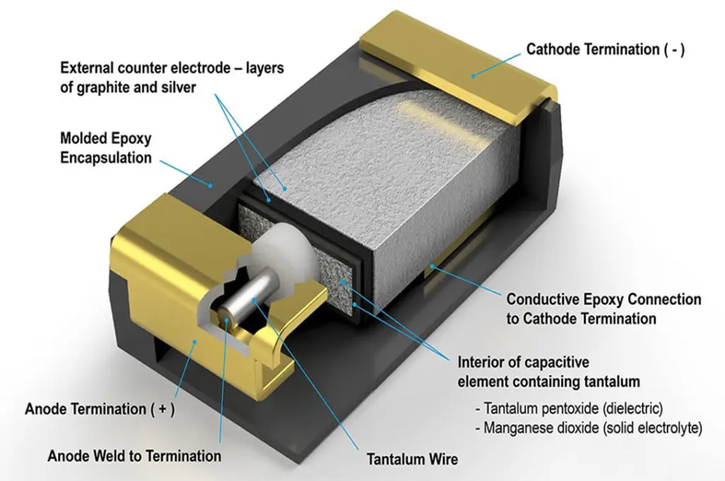
In MnO2 solid tantalum capacitors, the anode is impregnated with a manganese-nitrate solution that is thermally converted into manganese dioxide. Repeated impregnation and conversion steps develop coverage of the internal dielectric surface. Conductive-polymer capacitors instead use a polymer cathode system formed by processes appropriate to the particular construction. [1, 2, 3]
In conventional solid constructions, graphite and silver layers provide the outer cathode contact. They are applied over the cathode coating, not directly to bare tantalum metal. The anode wire and cathode contact are connected to the external terminations, and the element is encapsulated or enclosed before electrical ageing, screening and final inspection. [1, 3]
Wet tantalum capacitors use a liquid electrolyte to contact the dielectric-coated anode and a cathode structure associated with the case. Their assembly additionally requires reliable electrolyte containment and an appropriate lead-through seal. Figure 2 illustrates this distinction. [6]
Polymer and Manganese Dioxide Solid Tantalum Capacitors
MnO2 and conductive-polymer tantalum capacitors share a porous tantalum anode and Ta2O5 dielectric. Their main differences arise from cathode conductivity, behaviour at dielectric defects, environmental sensitivity and the screening used for the finished product. These differences affect power-supply design, leakage-sensitive circuits and qualification requirements. [1, 2, 4]
Tantalum powder and the processes needed to produce a reliable porous anode contribute to component cost. Capacitance, rated voltage, ESR, package construction, screening and procurement requirements all influence the final price. Compare application-qualified alternatives rather than assuming that one cathode technology is always cheaper or more reliable.
Tantalum Powder Technology and Specific Charge
Capacitor-grade powders are characterised by a specific-charge value commonly written as CV/g and expressed in µF·V/g. In this context, the voltage is the formation voltage used for the test anode, not automatically the rated voltage of a finished capacitor. The result depends on the stated pressing, sintering, formation and measurement conditions.
Eq. (5) defines the powder-specific charge SCV, where Ctest is the measured capacitance of the test anode, VF is its formation voltage and m is the mass of tantalum used in that test.
Higher specific charge can support smaller components or higher capacitance, but finished-component performance also depends on the formation-to-rating ratio, cathode penetration, anode geometry and package overhead. Powder-specific charge is therefore a technology indicator, not a substitute for the finished capacitor datasheet.
Dielectric quality is as important as surface area. Impurities, crystalline inclusions, oxygen vacancies and mechanical damage can create locally weak regions in the oxide. Material purity and process control influence leakage and breakdown behaviour, but no single powder parameter establishes the reliability of the assembled capacitor. [3]
Choosing Between MnO2 and Conductive Polymer
Conductive polymers generally have a lower cathode resistance than MnO2. This reduces ESR, improves capacitance retention at higher frequencies and can increase permissible ripple current for a given thermal design. Polymer also avoids the oxygen-rich MnO2 cathode involved in the traditional tantalum ignition mechanism. These advantages are particularly relevant to power-supply filtering and decoupling. [2]
MnO2 remains an established option where its leakage specification, environmental robustness, temperature capability or qualified procurement route suits the application. However, conductive-polymer tantalum capacitors are not restricted to consumer electronics. High-reliability and hermetically sealed polymer constructions are available, and suitability must be judged at series and ordering-code level. [2, 4]
For example, the KEMET T540/T541 high-reliability polymer datasheet provides screening options and distinguishes single-anode and multiple-anode constructions. It also identifies improved-humidity options rather than assigning the same humidity performance to every ordering code. This illustrates why a generic comparison of polymer against MnO2 is insufficient for aerospace, defence or long-life industrial procurement. [4]
For leakage-sensitive timing, hold-up or battery-powered circuits, compare the guaranteed leakage at the relevant voltage, temperature and electrification time. For power/SMPS applications, give additional attention to ESR versus frequency, ripple-current heating, transients and converter stability. The lowest available ESR is not automatically the correct choice for every control loop.
Rated Voltage, Category Voltage and Application Derating
Rated voltage VR applies under the conditions specified by the manufacturer. At elevated temperature, the maximum continuous voltage may fall to a lower category voltage VC. Application derating adds a design margin below the applicable voltage limit; it must not be confused with the formation margin built into the dielectric during manufacture. [1, 2, 4]
Define application derating D relative to the rated voltage using Eq. (6), where Vop,max is the maximum intended operating voltage, including the relevant ripple and transient allowance. Thus, 20% derating means operation at no more than 80% of rated voltage. The temperature-dependent category-voltage limit and any additional series requirements still apply.
For MnO2 tantalum capacitors in low-impedance circuits, such as directly connected supply inputs, substantial voltage derating and control of inrush current are important. A 50% derating level is an established starting point in manufacturer guidance, but more severe conditions can require greater margin or explicit current limiting. Less aggressive derating in a controlled, higher-impedance application requires support from the selected product’s guidance. A DC/DC output must not be assumed surge-free merely because it is an output. [1, 5]
For the conductive-polymer products covered by the KYOCERA AVX basic guide, typical recommendations are 10% derating for ratings up to 10 V and 20% for ratings of 16 V and above. The guide explicitly requires use of the relevant series datasheet and temperature curve. Do not extend the 10% recommendation universally through 16 V or apply these values to every manufacturer’s products. [2]
For a broader explanation of these terms, see capacitor voltage and temperature derating and category concepts.
Maximum catalogue voltage is a property of the technology and product range, not a universal physical boundary at a single voltage. Oxide integrity, powder morphology, formation conditions and cathode construction all constrain practical designs. Wet tantalum products must be considered separately from solid tantalum when discussing voltage capability. [1, 2, 6]
Case Sizes and Mechanical Identification
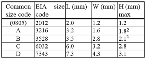
Surface-mount tantalum capacitors are supplied in a wide range of body sizes and heights. A case letter is not a universal mechanical specification: the same letter can describe different dimensions in different manufacturers’ ranges, and a common footprint does not establish identical height, termination geometry or land-pattern requirements.
Check the complete dimensional drawing, including maximum body dimensions, termination width and spacing, polarity indication and recommended land pattern. Use the supplier’s dimensional code and drawing rather than transferring a case letter alone between bills of materials. The KEMET T540/T541 datasheet, for example, specifies both manufacturer case letters and dimensional codes. [4]
For leaded parts and larger assemblies, provide mechanical support appropriate to the component mass and the specified shock and vibration environment. The electrical leads should not be assumed to provide adequate structural restraint.
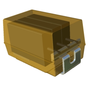
SMD Chip Construction Variants
Package construction affects the volume available for the anode, the current path and assembly inspection. Figure 6 shows established construction approaches; individual product drawings take precedence over the generic sketches.
- J-lead: bent metal terminations provide accessible solder joints and some mechanical compliance. Body height, termination geometry and assembly conditions remain series-specific.
- Undertab or facedown: terminations beneath the body can reduce mounting overhead and improve utilisation of the package volume. Hidden joints require an inspection strategy appropriate to the assembly; this construction is not inherently excluded from high-reliability use.
- Diced or wafer-based construction: small capacitor elements can be produced using a wafer-processing approach. These designs are often combined with bottom terminations to reduce package overhead.
- Conformal-coated construction: a protective coating surrounds the capacitor element without a conventional moulded body. Check body tolerances, handling and placement requirements rather than assuming the same assembly behaviour as a moulded chip.

Failure Modes and MnO2 Self-healing
Solid tantalum capacitors can develop increased leakage or a short circuit when a local dielectric defect becomes conductive. Whether a defect is isolated or progresses into a destructive failure depends on the defect, cathode system, available current and thermal conditions. Self-healing is a useful material mechanism, not a circuit-protection guarantee. [1, 3, 5]
In an MnO2 capacitor, current concentrated at a weak dielectric site produces local heating. Manganese dioxide can be converted locally to a more resistive lower oxide, reducing current through the defect. Oxygen transfer can also contribute to changes at the defective oxide region. This local isolation mechanism is involved in manufacturing electrical ageing and can occur during service. [3, 5]
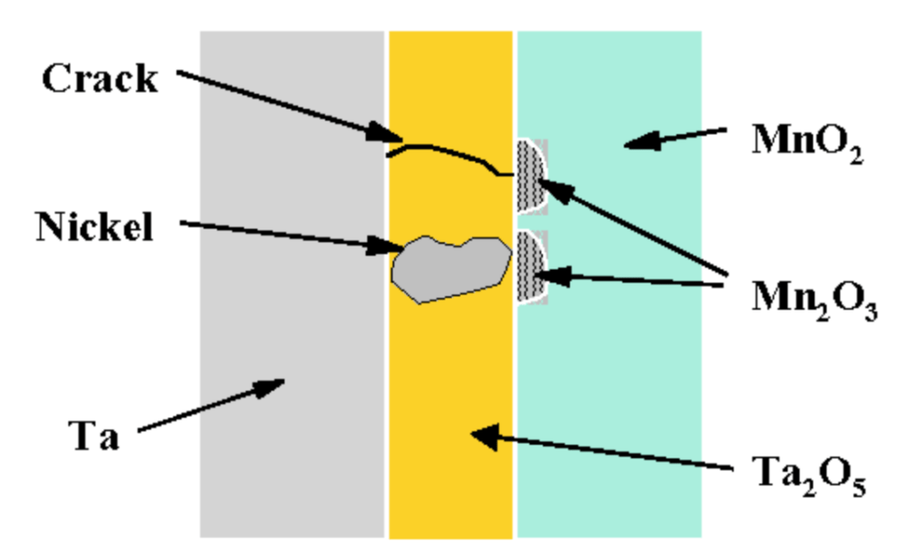
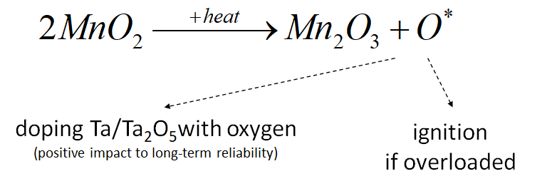
Successful isolation of a microscopic site need not cause a measurable change in total capacitance. It does not justify claiming zero effect on every electrical parameter or guaranteed recovery of every defective part. In a low-impedance circuit, electrical input can exceed the ability of the local mechanism to arrest the defect, producing a hard short circuit and potentially ignition. [5]
Scintillation describes a local breakdown event that may be followed by isolation. It should not be used as a synonym for an acceptable field failure. If a circuit exhibits abnormal leakage, repeated current events or thermal damage, assess the component and the surrounding circuit rather than assuming that self-healing has made continued service safe.
MnO2 Tantalum Capacitor Design Considerations
The following considerations are particularly important for power/SMPS inputs, battery-connected rails and other circuits with substantial fault-current capability. They also apply during in-circuit testing, where the available current and switching conditions can differ from normal service. [1]
- Control available fault and inrush current. Series impedance, controlled charging or another protection method can reduce the energy delivered into a defect. Where a physical resistor is unsuitable, use a capacitor and protection strategy supported for the actual low-impedance conditions.
- Apply voltage and temperature margins together. Include supply tolerance, ripple and transients, and follow the selected series guidance. Do not treat the laboratory surge-voltage rating as a permitted repetitive operating voltage.
- Use an approved screening and power-up procedure. Assembly can introduce stress not represented by incoming component tests. Controlled initial charging may reduce stress, but does not replace manufacturer screening or establish the remaining life of a component.
- Evaluate non-routine events. Hot-plugging, rapid restart, output shorts, supply collapse and test-fixture switching can create current and voltage stresses absent from the steady-state schematic.
- Check ripple-current heating in the installed assembly. Use ESR at the relevant frequencies and temperatures, then verify that local temperature and voltage remain within the applicable limits.
- Define the system response to a short circuit. Protection must consider source energy, disconnection time, nearby materials and the consequence of loss of the capacitor’s function.
A resistance-per-volt recommendation is application guidance under defined conditions, not a universal component property. Similarly, a surge-test circuit establishes performance under its stated voltage, resistance, temperature and repetition conditions; it does not provide a general formula for the safe surge current of an arbitrary capacitor. [1, 2]
Burn-in, Screening and Reliability Models
Electrical ageing and surge screening help identify early failures, but they do not make surviving parts immune to later overstress or environmental degradation. High-reliability procurement must identify the applicable component specification, exact screening option, test conditions and acceptance criteria. Requirements should not be inferred merely from a military, aerospace or automotive application label. [1, 4]
Manufacturer reliability models may use voltage, temperature and circuit-impedance correction factors or an acceleration factor derived from tests. These are empirical models for a specified product population and failure criterion. They are not universal laws that can be transferred between MnO2, polymer and wet tantalum products. [1, 4]
The KEMET high-reliability polymer datasheet, for example, provides a combined voltage and temperature acceleration approach and explicitly identifies its result as an estimate rather than a guarantee. Use the model and coefficients published for the selected series, within their stated scope, and distinguish catastrophic failure predictions from allowable parametric drift. [4]
Polymer Self-healing and Derating
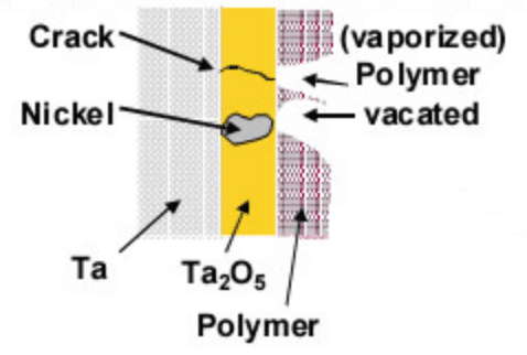
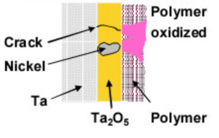
Conductive-polymer tantalum capacitors can isolate a dielectric defect through local changes in the polymer, including loss of electrical contact around the hot spot. This differs from the lower-oxide isolation mechanism of an MnO2 cathode. The absence of the oxygen-rich MnO2 cathode reduces the associated ignition risk, but a polymer capacitor can still fail electrically and dissipate dangerous energy if the circuit does not limit a fault. [2, 5]
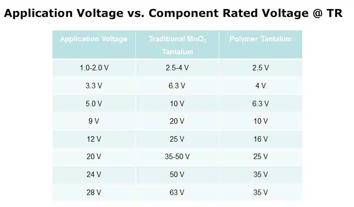
Polymer voltage derating is generally less severe than the margin commonly used for MnO2 tantalum in low-impedance circuits. It must nevertheless be combined with the temperature-dependent operating limit, ripple-current capability and the selected manufacturer’s surge guidance. The historical comparison in Table 3 is not a substitute for those requirements. [2, 4]
Electrical Model and Ripple Limits
A first-order model consists of capacitance C in parallel with a leakage resistance, with ESR and equivalent series inductance, ESL, in the current path. The leakage resistance is an operating-point approximation, because leakage is not generally a linear function of voltage. Frequency-dependent models better represent the distributed porous structure. [1, 2]
For a sinusoidal ripple-current component, Eq. (7) gives the approximate dissipated power P, where Irms is RMS current and ESR(f,T) is equivalent series resistance at frequency f and temperature T. Use amperes, ohms and watts.
For non-sinusoidal ripple, Eq. (8) sums the losses from the relevant frequency components. In,rms is the RMS current at harmonic frequency fn. This approach is useful when ESR differs appreciably across the switching-current spectrum. [1]
The approximate steady-state temperature rise ΔT is related to power through an effective thermal resistance Rth, expressed in K/W, as shown in Eq. (9). This resistance depends on the PCB, copper area, mounting, airflow and nearby heat sources; it is not simply an invariant property of the package.
Lower ESR can reduce heating or allow more ripple current, but the capacitor must also provide sufficient effective capacitance for the required transient response. In a converter output, both capacitance and ESR can affect control-loop behaviour. Verify the installed temperature rise rather than extrapolating a free-air rating without considering the assembly. [1, 2]
Terminal ripple voltage depends on the capacitor’s total impedance at the frequency of interest, not on ESR alone. The positive voltage peak must remain below the applicable operating limit, while the negative peak must not create unapproved reverse bias. Ripple-current and voltage checks are separate requirements. [1, 6]
ESR Reduction
Replacing MnO2 with a more conductive polymer is one way to reduce equivalent series resistance and capacitor losses. Anode geometry and the resistance of cathode contact layers provide additional opportunities. [1, 2]
In Figure 11, the conventional anode is compared with a fluted surface and a multiple-anode construction. Increasing the accessible outer contact area and shortening paths through the cathode material can reduce resistance between internal capacitance regions and the external cathode connection.
A multiple-anode design divides the active structure into elements connected electrically in parallel. For identical independent elements, parallel connection reduces their combined resistance, but a finished component also contains common contact and termination resistances. Its total ESR therefore need not decrease exactly in inverse proportion to the number of anodes. [2, 4]
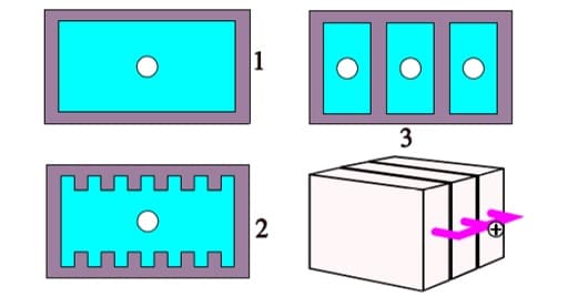
The frequency dependence of these improvements should be described in terms of distributed resistance and capacitance, rather than simply as classical conductor skin effect. At low frequency, dielectric losses can contribute strongly to the measured ESR. At higher frequency, resistance through the cathode, contact coatings and terminations becomes increasingly important. [1]
Graphite, silver, adhesive and leadframe interfaces contribute to the total resistance. Layer continuity, bonding and environmental stability therefore matter alongside the conductivity of the main cathode material. Compare guaranteed ESR at a stated frequency and temperature, and check how those limits change after endurance or humidity testing. [1, 4]
Reverse Voltage
Solid tantalum capacitors are polarised components and should not be designed for continuous reverse operation. A limited reverse-transient allowance in a manufacturer’s document is an exceptional operating condition, not a Zener-like voltage rating or permission to use the part as a non-polar capacitor. [1, 2]
Reverse limits differ between product families and decrease with temperature. For example, the KYOCERA AVX general tantalum guidance permits only specified short-term reversals, with limits defined by both a percentage of rated voltage and an absolute voltage ceiling. Its polymer guide gives different conditions. These values must not be combined into one generic reverse-voltage table. [1, 2]
If the selected datasheet does not explicitly permit the expected negative excursion, prevent that excursion through circuit design or choose a suitable non-polar technology. Evaluate power-down, rail sequencing, AC coupling and switching undershoot as well as normal steady-state polarity. High-reliability applications require the applicable procurement and design rules, not extrapolation from short-duration breakdown observations.
Assembly, Moisture Sensitivity and Environmental Exposure
Reflow, rework and board flex can stress the dielectric, cathode contacts and encapsulation. Follow the selected series limits for peak temperature, time, heating rate and permitted process cycles. A generic tantalum soldering profile is not sufficient evidence for a particular polymer construction. [2, 4]
Check moisture sensitivity level, dry-pack handling and floor-life requirements before assembly. Moisture sensitivity during soldering and resistance to long-term operating humidity are different characteristics. A component with suitable reflow handling can still require a specific humidity-qualified option for service in a warm, humid environment. [2, 4]
Conductive-polymer capacitors can exhibit changes in ESR, capacitance and leakage behaviour with temperature, moisture exposure and drying. Hermetic and enhanced-humidity constructions address particular environmental requirements, but should not be assumed electrically or mechanically interchangeable with a standard moulded part. [2, 4]
Solid Tantalum Electrical Characteristics
Capacitance, ESR, dissipation factor and leakage current describe different aspects of capacitor performance. Their values depend on measurement conditions, and a typical characteristic curve does not replace the guaranteed limits for an individual part number. The following plots illustrate the main relationships for solid tantalum capacitors.
Capacitance Versus Temperature
Solid tantalum capacitance generally increases with temperature and decreases at lower temperature. The change depends on the construction, rated voltage and measurement frequency. Separate initial capacitance tolerance from temperature-related change and from the additional changes permitted after endurance, humidity or assembly testing. [1, 4]

A single generic statement such as capacitance stability within ±5% is insufficient for component selection. For example, the KEMET T540/T541 specification distinguishes room-temperature tolerance from larger permitted temperature changes and gives different temperature-stability limits for some higher-voltage ratings. Build the minimum and maximum capacitance budget from the actual datasheet conditions. [4]
Capacitance Versus Frequency
The porous anode contains many local capacitance regions connected through finite cathode resistance. At increasing frequency, regions reached through longer or more resistive paths contribute less to the measured capacitance. This distributed resistance-capacitance behaviour produces capacitance roll-off rather than a frequency-independent lumped capacitance. [1, 2]
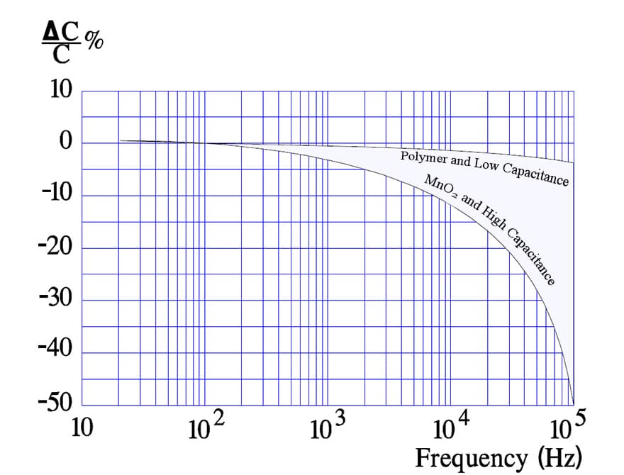
Conductive polymer generally improves high-frequency capacitance retention because it lowers the resistance connecting internal capacitance regions to the cathode terminal. Anode geometry also matters. A finer powder may provide more low-frequency capacitance while making the internal paths more demanding to access at high frequency. [1, 2]
Figure 15 retains the original comparison of 470 µF, 6.3 V MnO2 tantalum designs. The multiple-anode approach shortens internal current paths and can improve both ESR and the usable capacitance at higher frequency. Polymer capacitors already benefit from a more conductive cathode, but multiple-anode polymer constructions can still provide a useful ESR reduction. [2, 4]
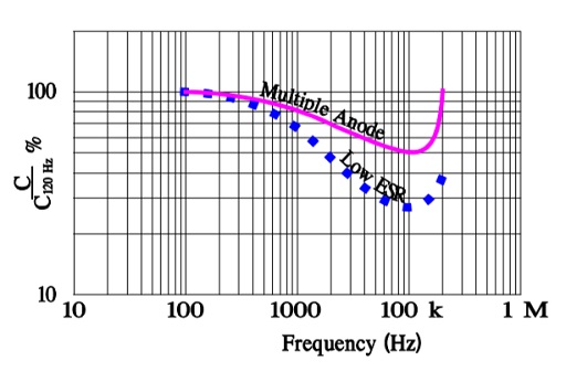
For power/SMPS filtering, compare effective capacitance across the frequencies relevant to ripple and load transients. For timing or low-frequency signal circuits, low-frequency capacitance and leakage may matter more. Above self-resonance, the component becomes predominantly inductive, so extrapolating a capacitance-only model is no longer appropriate. [1]
ESR Versus Temperature
The ESR of both MnO2 and conductive-polymer tantalum capacitors is comparatively stable over temperature relative to many liquid-electrolyte constructions. However, it is not temperature-independent. Cathode material, contact layers, frequency and environmental history all affect the result. [1, 2]
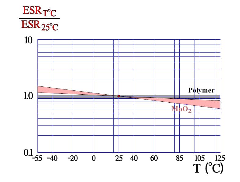
Do not calculate the worst-case ripple temperature rise from a room-temperature typical ESR curve alone. Use guaranteed ESR limits and any applicable temperature factors, then consider the allowed change after endurance and environmental exposure. The resulting component temperature must remain within the selected series limits. [1, 4]
ESR Versus Frequency
ESR is frequency-dependent because several loss mechanisms contribute to the measurement. At lower frequencies, dielectric losses can be significant; at higher frequencies, the cathode system, contact layers and terminations become more important. The ESR value specified at 100 kHz must not automatically be used at 120 Hz or throughout a wide switching spectrum. [1]
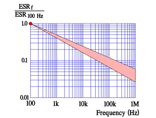
Normalised plots describe relative change, not absolute resistance. Two technologies can have similar normalised curves while differing substantially in milliohms. For a replacement assessment, compare the actual guaranteed ESR, impedance and ripple-current capability of the proposed part numbers. [1, 2, 4]
Dissipation Factor Versus Frequency
Dissipation factor, DF, is commonly expressed as tan δ or as a percentage equal to 100 tan δ. It is not the same quantity as ESR. For a series-equivalent capacitor model in the capacitive region, Eq. (10) relates tan δ to ESR, capacitance C and angular frequency ω, where ω = 2πf and f is frequency in hertz. Use C and ESR evaluated at the same frequency. [1]

Figures 17 and 18 show why ESR can fall with increasing frequency while dissipation factor rises: Eq. (10) also contains frequency and capacitance. The relationship does not justify assuming a fixed capacitance at all frequencies or extending the simple capacitive model beyond self-resonance.
Check whether a datasheet expresses DF as a dimensionless number or a percentage. A value of 0.1 for tan δ corresponds to 10%, not 0.1%. Also check measurement amplitude, DC bias, temperature and the equivalent-circuit model used by the instrument. [1]
DC Leakage Current and Its Measurement
DC leakage current, commonly abbreviated DCL, is measured after a specified time at an applied DC voltage. It depends on voltage, temperature, time since energisation and prior environmental exposure. Immediately after voltage is applied, charging and absorption currents can make the measured current much higher than the stabilised leakage value. [1, 2]
For an explanation of these measurement effects, see capacitor leakage-current characteristics. In production testing, reproduce the datasheet electrification time and conditions before comparing a result with its guaranteed limit.
Some MnO2 tantalum series use a maximum leakage expression based on 0.01CV, with C entered numerically in µF, rated voltage V entered in volts and the result obtained in µA. Many polymer series use a higher coefficient, such as 0.1CV. These are specification conventions, not universal leakage laws. A series may also impose a minimum leakage allowance or a different coefficient. [1, 4]
Eq. (11) makes the units explicit. IDCL,lim is the specified leakage limit, CR is rated capacitance, VR is rated voltage and aDCL is the numerical coefficient stated for the series. Apply any additional minimum-current term and temperature condition given in the datasheet.
For the original 100 µF, 10 V example, a coefficient of 0.01 gives a maximum leakage of 10 µA at the specified test conditions. A coefficient of 0.1 gives 100 µA. The arithmetic is unchanged, but the limits apply only to a product whose specification uses the corresponding expression. The KEMET T540/T541 datasheet, for example, specifies 0.1CV after five minutes at rated voltage. [1, 4]
A typical measured value can be lower than the maximum, but an assumed factor of ten is not a guaranteed design margin. For a battery-life or precision-timing calculation, use a guaranteed limit at the relevant conditions or an application-specific limit agreed with the supplier.
Leakage Current Versus Temperature
Leakage generally increases with temperature. Figure 19 illustrates the trend, but the magnitude and permitted limit depend on the series. A normalised comparison does not establish identical absolute leakage, temperature multipliers or stabilisation time for MnO2 and polymer products. [1, 2, 4]
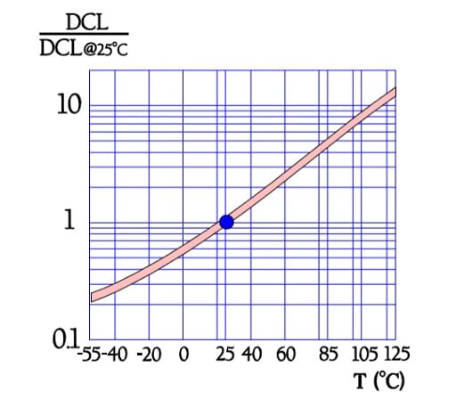
Polymer leakage stabilisation can also depend on moisture state. A dry component immediately after reflow may take longer to reach a low current than one that has equilibrated with ambient humidity. This behaviour is particularly relevant to short-duration in-circuit tests and cold-start measurements; the test threshold and waiting time must match the intended acceptance criterion. [2]
Leakage Current Versus Applied Voltage
Reducing applied voltage below rated voltage generally reduces leakage, often nonlinearly. Figure 20 illustrates the relationship. A typical curve can support an engineering estimate, but cannot create a guaranteed leakage limit at a voltage for which the manufacturer has not specified one. [1]

In the original 100 µF, 10 V MnO2 example, a 10 µA limit at rated voltage does not establish a 1 µA maximum at 5 V. Likewise, a further reduction to 0.1 µA cannot be treated as a guaranteed typical value. Leakage may fall substantially under derating, but a design requiring a particular 5 V leakage limit needs suitable supplier data or qualification.
When comparing alternative voltage ratings for a fixed application voltage, do not assume that choosing the highest voltage rating always gives the lowest leakage. The rated-voltage leakage expression, internal construction and voltage dependence can all change. Compare the proposed part numbers at the application operating point. [1]
Simulation Models and Measurement Practice
Manufacturer tools can provide part-number-specific typical capacitance, ESR and impedance curves, equivalent circuits and, for some products, downloadable models or S-parameters. KYOCERA AVX identifies SpiTan for these purposes, while KEMET provides K-SIM. Model availability and the included effects differ by product. [2, 4, 8]
A model should be checked for its frequency range, temperature assumptions, DC-bias conditions and treatment of leakage. Do not assume that a frequency-domain model also predicts dielectric breakdown, surge survival, ageing, moisture effects or the statistical limits of a production population.
- Measure capacitance and DF at the specified frequency, AC amplitude, DC bias and temperature. A low-frequency nominal capacitance measurement is not a direct measurement of high-frequency usable capacitance.
- Measure ESR at the specified frequency and with an appropriate fixture. At low milliohm levels, contact resistance and fixture compensation can materially affect the result.
- Measure leakage after the specified electrification time, using the prescribed voltage and current-limiting arrangement. Allow for instrument and fixture leakage when measuring small currents.
- Use guaranteed initial and post-test limits for acceptance. Use typical curves and simulation models to understand behaviour, not to replace contractual limits.
Solid Niobium and Niobium Oxide Capacitors
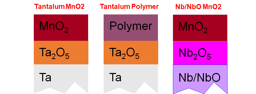
Niobium-based capacitors use an Nb2O5 dielectric instead of Ta2O5. Niobium-metal capacitors and niobium oxide capacitors are related but distinct constructions: in the latter, the conductive anode material is NbO. The commercially established NbO construction discussed here combines that anode with an MnO2 cathode system. [5, 8]
NbO capacitors are an option for low-voltage circuits where their fault behaviour, stable electrical characteristics and available procurement route suit the application. Their voltage range, ESR, package volume and sourcing options must be compared with the specific tantalum, polymer, ceramic or aluminium alternatives, rather than with a generic technology label. [1, 5, 8]
Brief History and Commercial Context
Interest in niobium-based capacitors increased around the tantalum supply disruption in 2000. Development sought both a different raw-material route and electrical characteristics suitable for compact, low-voltage electronics. Conductive NbO provided an alternative anode material that could be processed into a porous structure using a manufacturing approach related to conventional tantalum technology. [5]
Early development involved challenges in powder quality, leakage, dielectric stability and manufacturing control. Niobium-metal and NbO developments should not be treated as a single product history, because the choice of anode material changes the interface with the dielectric and the behaviour at a fault. [5]
Conductive-polymer tantalum developed into a major alternative for low-ESR applications, while NbO products retained a different balance of characteristics. The commercially established NbO products described here use MnO2; a polymer tantalum specification must not be transferred to an NbO component merely because the packages resemble each other. [2, 5, 8]
For new designs, lifecycle status is as important as historical availability. The KYOCERA AVX NOS product page includes a notice concerning selected end-of-life part numbers. Check the exact orderable code and its product-change notices; a family page does not establish that every capacitance, voltage and package combination remains available. [8]
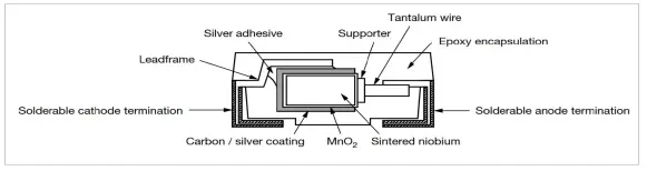
Anode, Dielectric and Volumetric Efficiency
NbO is electrically conductive and can serve as the porous anode. Nb2O5 is the insulating dielectric formed on its surface. MnO2 provides the solid cathode contact to the dielectric, followed by conductive outer layers and terminations. Confusing these three oxides obscures both the construction and the fault-isolation mechanism. [1, 5, 8]
The dielectric constant alone does not determine the finished capacitance density. Dielectric growth rate, permissible operating field, powder morphology, accessible surface area and packaging also matter. A higher dielectric constant can be offset by a thicker dielectric or less favourable anode geometry, as the capacitance relationship in Eq. (1) shows. [1]
The lower mass density of an anode material does not, by itself, prove that twice the material volume is required to store the same charge. Mass-specific charge and volume-specific charge are different quantities. Compare finished parts using a consistent package-volume definition and the capacitance available at the required operating conditions.

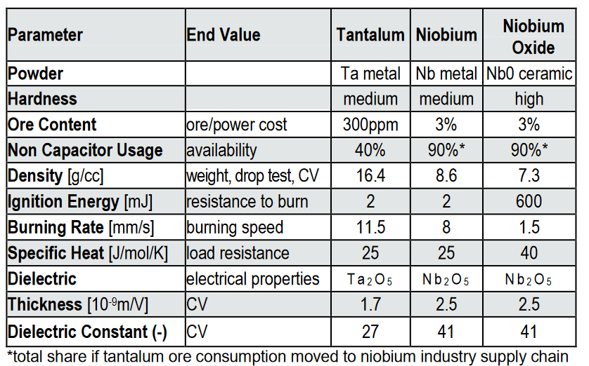
Raw Materials, Cost and Availability
Niobium-based development offered an alternative to dependence on capacitor-grade tantalum powder. NbO and MnO2 provide a different material combination, but raw-material abundance does not guarantee a lower finished-component price or a broader supply base. [5, 8]
For purchasing decisions, compare approved manufacturers, orderable codes, lead times, minimum order quantities and lifecycle commitments. A niche component with attractive material economics may still carry greater sourcing risk than a widely available alternative.
Ignition Behaviour and Its Limits
NbO has greater resistance to ignition than a tantalum-metal anode under the conditions considered in the manufacturer’s technology discussion. This characteristic and the additional self-arresting mechanism are important reasons to consider NbO capacitors where fault behaviour matters. [5]
Reduced ignition risk is not equivalent to guaranteed non-flammability of an assembly under every electrical fault. Reverse bias, excessive ripple current, overvoltage or externally supplied fault energy can damage a component. A system-level assessment must still consider the power source, protective devices, nearby materials and the loss of the capacitor’s intended function. [5]
Niobium-metal and NbO anodes should not be assigned identical ignition behaviour. The safety discussion in this section concerns the NbO construction and its specified operating conditions, not every capacitor containing niobium.
Sub-oxides and the Self-arresting Mechanism
The different electrical properties of niobium oxides are central to NbO capacitor behaviour. NbO is the conductive anode material, Nb2O5 is the principal dielectric and NbO2 can provide a more resistive region at a locally damaged interface. [5]
In addition to MnO2 cathode self-healing, local heating at a dielectric defect can form a resistive NbO2 region between the anode and the dielectric. This additional restriction of fault current is described as self-arresting. It reduces the likelihood that local dielectric breakdown develops into a low-resistance short circuit. [5]
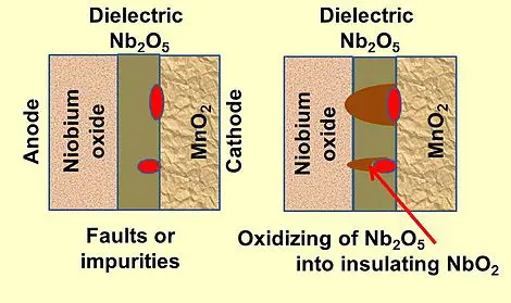
Self-arresting does not mean that the original dielectric is fully restored or that every parameter remains unchanged. A component that has experienced breakdown may exhibit increased leakage or other changes. Continued acceptability must be judged against the electrical specification and the system’s fault-handling requirements, not inferred from the absence of a hard short.
Operating Temperature and Voltage
NbO products require their own voltage-versus-temperature limits. The maximum operating temperature does not necessarily permit operation at full rated voltage, maximum ripple current and maximum ambient temperature simultaneously. Apply the category-voltage and ripple-current curves for the selected series. [1, 8]
The KYOCERA AVX NOS product page specifies an operating-temperature range of −55 °C to +125 °C and a rated-voltage range extending to 8 V. It separately describes rail voltages up to 5.5 V. These are different limits: 8 V is not a blanket application-voltage recommendation for the NOS range. [8]
The original article’s 8 V application example was based on applying 20% derating to a 10 V-rated component. The calculation is correct: 0.8 × 10 V = 8 V. However, it does not establish that a currently available 8 V-rated product can operate on an 8 V rail, or that a particular 10 V product remains available and suitable at elevated temperature. [1, 5, 8]
For comparison, 20% derating of an 8 V rating gives 6.4 V before any additional temperature or manufacturer-specific restriction. This arithmetic must not override the lower recommended rail voltage or category-voltage limit of the selected product. Include supply tolerance and ripple peaks when checking the application.
A blanket reliability ranking such as better than tantalum below 85 °C, equal at 105 °C and inferior at 125 °C is not a substitute for product data. Reliability figures depend on the reference voltage, temperature, circuit impedance, confidence level and failure definition. Compare like-for-like conditions. [1]
Capacitance Versus Temperature
Niobium-based capacitors exhibit temperature-dependent capacitance. Figure 24 retains the original illustrative curves; their purpose is to show the trend, not to establish a universal tolerance for every niobium-metal or NbO construction. Use the selected series limits when calculating minimum capacitance at low temperature.
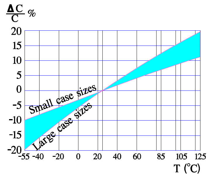
Initial tolerance, temperature change and allowed post-endurance drift must be treated separately. A typical curve does not establish the guaranteed capacitance available at the end of the intended service period. [1]
Capacitance Versus Frequency
As in solid tantalum, distributed resistance within the porous structure causes effective capacitance to decrease with frequency. Powder morphology and cathode penetration influence this behaviour. Niobium-based material identity alone does not establish the porosity or frequency response of a finished part. [1]
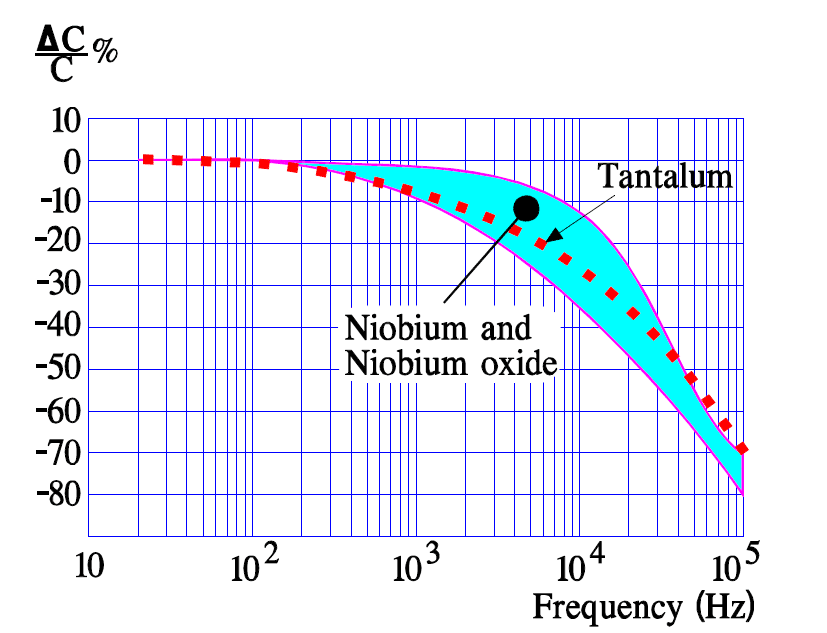
For an SMPS output, compare usable capacitance and ESR over the relevant frequency range rather than assuming that matching nominal capacitance produces the same transient response. For low-frequency decoupling or timing, leakage and temperature behaviour may be more important than high-frequency roll-off.
ESR Versus Temperature and Frequency
The MnO2 cathode system makes an important contribution to the ESR of conventional NbO capacitors. Their general ESR behaviour is therefore related to that of MnO2 tantalum, but package geometry, contacts and anode construction also contribute. Similar technology does not imply identical guaranteed ESR. [1, 8]
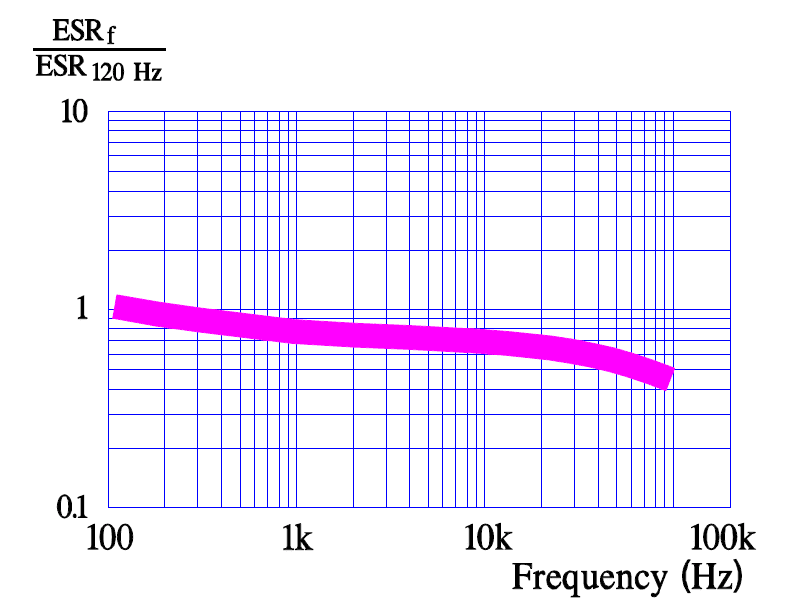
The convergence of particular curves at higher frequency should not be generalised into a claim that the technologies have negligible impedance differences throughout the megahertz range. Near and above self-resonance, package inductance, terminal geometry and the mounting arrangement can dominate impedance. [1]
For ripple-current selection, use the ESR at the relevant frequency and the permissible dissipation for the chosen case and temperature. Thermal performance in the installed PCB must be checked independently of a normalised electrical comparison. [1]
Leakage Current Versus Temperature
NbO leakage depends on applied voltage, temperature and electrification time. Its guaranteed limit may use a different CV coefficient or minimum-current term from an MnO2 tantalum part. The manufacturer’s application guide lists different leakage ranges for different tantalum and OxiCap products, so a fixed technology-wide leakage multiplier is not appropriate. [1]
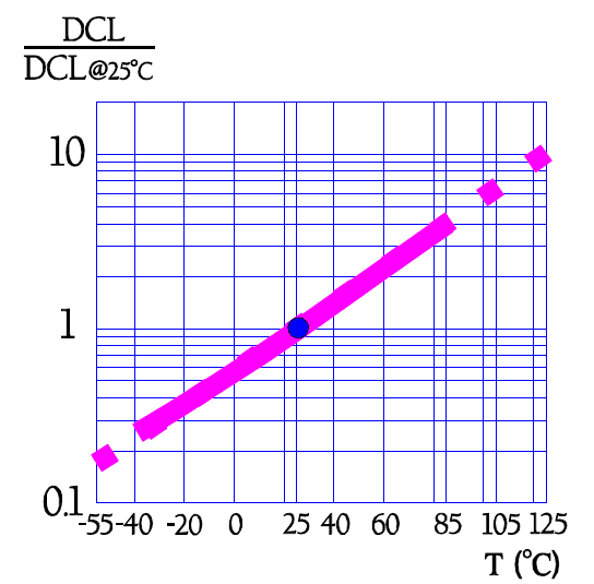
Low-power applications should budget leakage using the selected product’s maximum at the relevant conditions. Self-arresting behaviour does not establish low normal-operating leakage, and a typical room-temperature measurement does not establish a hot-temperature maximum.
Applications
NbO capacitors can be considered for low-voltage applications that do not require the lowest ESR available from conductive-polymer alternatives. Their potential value lies in the combination of capacitance density, stable behaviour under DC bias, mechanical construction and reduced likelihood of a low-resistance fault. [5, 8]
- Consumer electronics: low-voltage bulk decoupling and control electronics where the electrical limits and installed cost compare favourably with aluminium electrolytic or ceramic alternatives.
- Industrial equipment: low-voltage control and monitoring circuits where leakage, temperature, fault behaviour and long-term component availability have been evaluated.
- Automotive electronics: suitable low-voltage rails in cabin electronics, infotainment and control equipment, using a product with the required qualification and temperature capability.
- Aircraft and defence equipment: selected low-voltage functions where the procurement specification, screening, environmental evidence and system-level failure analysis support the part.
- Medical equipment: only where the specific product approval, environmental conditions and consequences of failure satisfy the equipment’s requirements. A generic technology description is not evidence of suitability for implantation or a life-support function.
The NOS product page identifies transportation and automotive DC/DC applications and states that the series meets AEC-Q200 requirements. This is a component qualification statement, not certification of a complete safety function. Verify the exact part number and applicable qualification documentation. [8]
Limitations, Substitution and Sourcing
The main selection constraints are the available voltage and capacitance combinations, ESR, package volume, temperature-dependent operating limits and the number of suitable sources. These constraints may outweigh the technology’s favourable fault behaviour in a particular design. [1, 5, 8]
A tantalum or polymer capacitor with a matching footprint is not automatically a drop-in replacement for NbO, or vice versa. Compare polarity, maximum dimensions, land pattern, effective capacitance, ESR, leakage, ripple current, surge behaviour, voltage derating and qualification. A change of ESR can also affect converter stability and damping.
Where second sourcing matters, qualify the alternative before production rather than treating a common package outline as evidence of interchangeability. Include assembly-profile compatibility, inspection requirements and lifecycle notices in the substitution record.
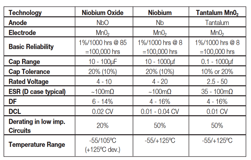
Niobium and NbO Summary
NbO capacitors provide an additional option for appropriately derated low-voltage circuits. Their self-arresting mechanism and resistance to ignition can be useful selection factors, but they do not guarantee an open-circuit failure mode or eliminate the need for circuit protection. Select them using current part-number data, not historical maximum voltage ranges or unqualified claims of short-circuit immunity. [1, 5, 8]
Wet Electrolytic Tantalum Capacitors
Wet tantalum capacitors combine a porous tantalum anode, a Ta2O5 dielectric, a liquid electrolyte and a cathode structure within the case. They are useful where compact energy storage, low leakage and environmental performance justify their cost and assembly requirements. Their electrical limits depend strongly on the cathode system, case construction and individual product series. [6]
Positioning and Applications
Typical applications include voltage hold-up, energy storage, filtering and pulse-power systems in industrial, avionics, defence and aerospace equipment. Specialised medical constructions also exist, but medical suitability must be established for the particular product and application rather than inferred from the capacitor technology. [6]
Wet tantalum can offer high capacitance per installed volume and low DC leakage, particularly in hermetically sealed constructions. However, it is not automatically the smallest, lowest-ESR or most economical solution at every rating. Compare actual parts against aluminium electrolytic, aluminium-polymer, solid tantalum, film and other candidates at the required voltage, temperature and discharge duty.
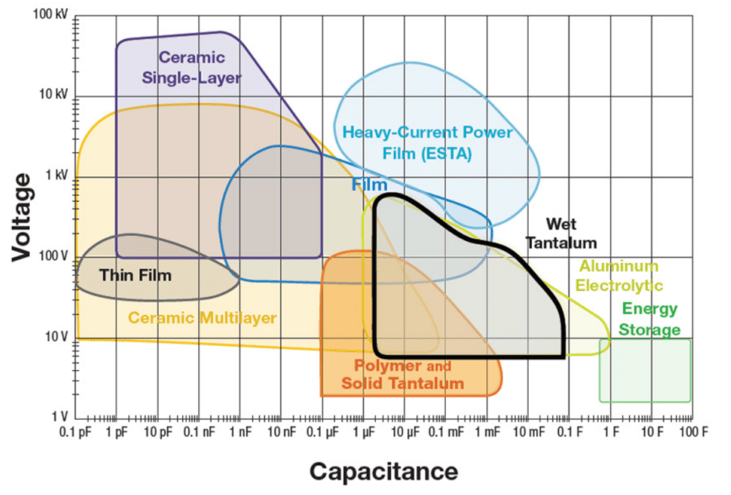
Vishay’s wet-tantalum application note describes wet-slug products with ratings up to 150 V DC. This does not establish a universal maximum for every specialised wet tantalum construction, and it shows why a 125 V ceiling must not be applied to the whole tantalum capacitor family. [6]
The same note describes capacitance-volume advantages over aluminium electrolytics, but such comparisons depend on the selected ratings and construction. A dielectric-constant ratio or a broad historical comparison cannot establish the installed-volume advantage of a particular modern part. [6]
Conventional and High-capacitance Cathode Systems
A conventional wet tantalum design uses a sintered tantalum cathode structure within the case. Other constructions use a proprietary high-area cathode coating. Both contain liquid electrolyte, but their cathode capacitance, resistance and reverse-transient behaviour can differ substantially. [6, 7]
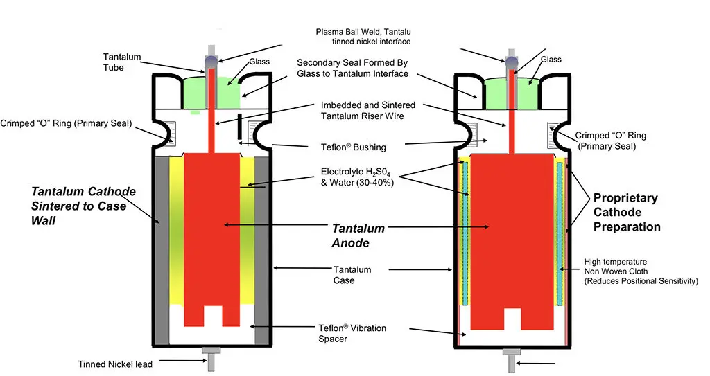
The terminal capacitance is influenced by both the anode and cathode interfaces. Increasing cathode capacitance reduces its limitation on the complete device, allowing more of the anode’s capacitance to be used. A higher-area cathode can also improve other characteristics, but the improvement must be taken from the actual product specification. [6, 7]
The original article attributed a universal threefold capacitance advantage to a formation voltage one-third that of a solid capacitor. That is not an appropriate general rule. Formation margin, anode geometry, cathode capacitance and package overhead differ between products; they cannot be reduced to a fixed wet-versus-solid ratio.
Historically, tantalum foil constructions also existed. They are distinct from the porous-anode wet capacitors discussed here and should not be confused with current wet-slug or high-energy designs.
Case Construction and Mechanical Mounting
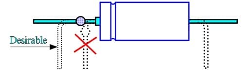
Axial wet tantalum capacitors are supplied in established cylindrical case families, including T1 through T4 and additional variants. Case designations do not replace a dimensional drawing: insulated diameter, body length, lead material and lead length must all be checked. [6, 7]
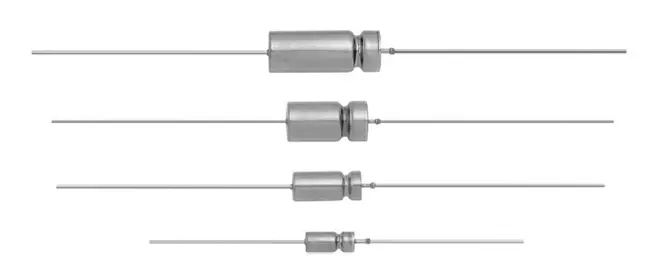
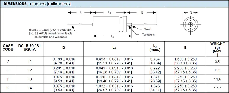
Provide mechanical restraint appropriate to component mass, orientation, shock and vibration. The leads and solder joints should not be the only structural support where the environmental loads require additional restraint. A capacitor qualified for a particular shock or vibration test is not evidence that an arbitrary PCB mounting arrangement will withstand the same environment. [7]
Do not transmit lead-forming forces into the glass-to-metal seal or the tantalum riser connection. Follow the manufacturer’s permitted bend location and tooling instructions. Where a nickel external lead is welded to a tantalum section, identify the weld and seal location before forming the lead.
Electrolyte, Seals and Case Materials
Conventional wet tantalum capacitors use an acid electrolyte whose formulation is selected for the construction and operating-temperature range. The electrolyte provides ionic contact between the dielectric-coated anode and the cathode system. Seal integrity is essential to retaining the electrolyte and preventing corrosive leakage. [6]
Do not assign one freezing point to every wet tantalum electrolyte. Acid concentration, additives and immobilisation methods affect low-temperature behaviour. Use the capacitor’s specified low-temperature capacitance, impedance and operating limits rather than inferring performance from a single chemical-property value.
Silver-case and tantalum-case constructions have both been used. Their seal designs, reverse-voltage behaviour and failure mechanisms differ. Vishay’s application note distinguishes conventional silver-case products from all-tantalum hermetically sealed designs and identifies the latter for demanding environments. [6]
Hermetic construction reduces electrolyte-loss risk, but it does not justify claiming that every wet tantalum capacitor is immune to leakage or has unlimited life. Mechanical damage, manufacturing defects and operation outside the specified conditions can compromise the enclosure or electrical performance. [6, 7]
Rated Voltage, Category Voltage and Derating
Many wet tantalum series permit operation near rated voltage below their reference temperature, provided that DC bias, ripple and transients remain within the specified limits. This differs from the substantial application derating commonly used for MnO2 solid tantalum in low-impedance circuits. It does not eliminate the value of a reliability guard band. [6]
Vishay’s general wet-tantalum note recommends a 10% to 20% guard band for increased reliability and explains that the margin should be applied relative to category voltage at higher temperature. The precise category-voltage curve must come from the selected series rather than from a universal wet-tantalum rule. [6]
The DLA 93026 datasheet illustrates the importance of rating-specific limits. It lists 25 V at 85 °C with 15 V at 125 °C for one rating group, and 125 V at 85 °C with 85 V at 125 °C for another. Neither group is represented exactly by applying one fixed two-thirds multiplier to every rating. [7]
Use the maximum intended terminal voltage, including ripple peaks, when selecting the DC working point. Where a datasheet separately defines a surge rating, interpret it under its stated conditions and the applicable procurement rules; do not assume that it permits indefinite or repetitive operation above rated or category voltage. [6, 7]
Reverse Voltage
Reverse capability depends on the complete cathode and case construction, not simply on the presence of a liquid electrolyte. Vishay identifies particular conventional tantalum-case styles with reverse-voltage capability, while conventional silver-case designs do not receive the same allowance. The limits must be checked for the exact series and conditions. [6]
The DLA 93026 datasheet prohibits continuous reverse voltage, but permits transient reverse surges only when all its conditions are met: peak reverse voltage no greater than 1.5 V, peak current multiplied by transient duration no greater than 0.05 A·s, and a repetition rate below 10 Hz. This is a series-specific exception, not a general permission for wet tantalum capacitors. [7]
Check reverse excursions during discharge, rail sequencing, series-bank imbalance and supply collapse. If the selected product does not explicitly permit the expected event, prevent it through circuit design. A blanket statement that every proprietary high-capacitance cathode permits no reverse transient is as inaccurate as assigning every wet tantalum capacitor a 3 V reverse allowance.
Capacitance Versus Temperature
Wet tantalum capacitance can decrease substantially at low temperature as electrolyte conductivity falls and internal charging time constants increase. The amount of change depends on the design and rating. High nominal capacitance does not establish adequate usable capacitance during a cold-start or short discharge event. [6, 7]
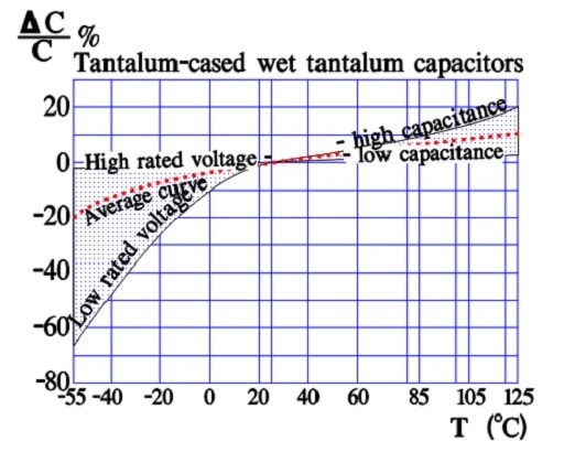
For example, the DLA 93026 standard-ratings table specifies different low-temperature capacitance changes for different capacitance-voltage combinations. The largest permitted decreases must not be replaced by a generic wet-tantalum temperature coefficient. Use the guaranteed value applicable to the selected part number. [7]
Initial capacitance tolerance and temperature change are separate. A hold-up design must account for both, together with the effects of discharge duration, ESR and any permitted change after endurance.
Capacitance Versus Frequency
The electrolyte-filled pore network creates a distributed resistance-capacitance structure. As frequency increases, internal regions reached through more resistive paths contribute less to measured capacitance. Low temperature can make this effect more pronounced by increasing electrolyte resistance. [6]
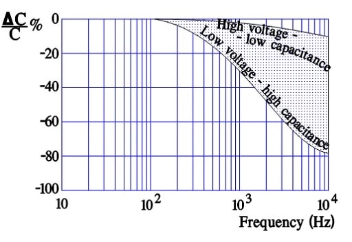
Fine powder and a large internal area can increase low-frequency capacitance while making the frequency response more demanding. Compare the actual effective capacitance and impedance needed by the circuit rather than assuming that a higher catalogue capacitance always improves transient performance.
A capacitance-versus-frequency plot cannot by itself establish a temperature characteristic. Evaluate temperature using the relevant temperature data, and frequency using the stated measurement conditions. Cross-comparison requires curves or a model that explicitly covers both variables.
ESR Versus Temperature
Electrolyte resistance contributes to wet tantalum ESR and typically becomes more significant at low temperature. Cathode construction and internal contacts also matter. Consequently, an ESR value measured at room temperature cannot establish cold-start voltage droop or permissible cold-temperature ripple current. [6, 7]
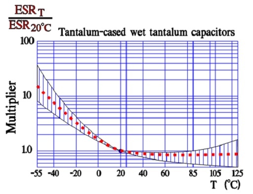
Where a datasheet specifies low-temperature impedance rather than ESR, preserve that distinction. Impedance contains both resistive and reactive contributions. It cannot always be substituted directly for ESR in a thermal calculation. [7]
ESR Versus Frequency and Ripple-current Capability
Wet tantalum ESR varies with frequency, and the frequency used for a catalogue ESR measurement may differ from the frequency used for its ripple-current rating. The DLA 93026 datasheet, for example, specifies maximum ESR at 120 Hz and lists ripple-current ratings at 40 kHz and 85 °C, together with correction factors. [7]
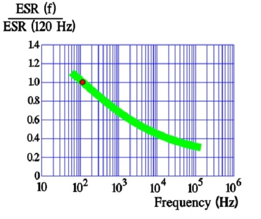
Use Eqs. (7) to (9) to relate ripple current, losses and temperature rise, with ESR appropriate to the ripple spectrum. The permissible ripple current is also constrained by ambient temperature, voltage utilisation and the specified cooling conditions. A component’s maximum voltage, temperature and ripple-current figures are not independent ratings that can necessarily be combined. [6, 7]
For pulse applications, average thermal loading is only part of the assessment. Check peak current, pulse width, repetition rate, ESR voltage drop and the manufacturer’s pulse-duty guidance. A ripple-current rating alone does not qualify an arbitrary discharge pulse.
Leakage Current Versus Temperature
Low leakage is an important reason to select wet tantalum for energy retention and low-power functions. Nevertheless, leakage is finite and depends on voltage, temperature, electrification time and construction. Use the specified limit rather than a comparison with an unrelated capacitor dielectric. [6, 7]
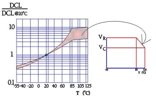
A bend or flattening in a normalised leakage curve can reflect a change in applied test voltage above the reference temperature. It does not prove that leakage at a constant voltage stops increasing. Check whether the underlying measurements use rated voltage, category voltage or a fixed application voltage.
The DLA 93026 datasheet gives separate room-temperature and elevated-temperature leakage limits by rating. These limits should be used directly when assessing stored-energy loss or standby consumption. [7]
Leakage Current Versus Voltage
Wet tantalum leakage generally falls as applied voltage is reduced, but the dielectric-electrolyte system is not a simple linear resistor. A typical normalised curve does not establish a universal voltage exponent or a guaranteed lower-voltage leakage limit. [6]
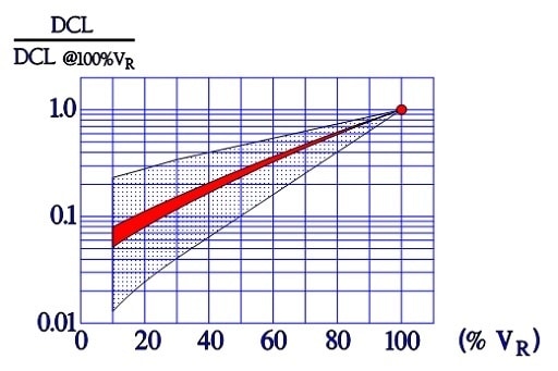
When leakage is a critical acceptance parameter, specify the voltage, temperature, waiting time and allowable current. Do not infer a guaranteed limit from a visual comparison between wet and solid tantalum curves.
Failure Modes and Handling Precautions
Wet tantalum failure assessment must cover both electrical faults and electrolyte containment. Possible outcomes include increased leakage, a short circuit, excessive ESR, loss of capacitance or leakage through a damaged seal. A generic statement that seal leakage is always the most common failure mode requires evidence for the particular product population and service conditions.
Lead forming, soldering, mechanical mounting and temperature cycling can impose stresses on the enclosure and lead-through. Follow the selected series requirements and confirm that the relevant environmental qualification covers the intended use. The DLA 93026 specification, for example, identifies seal, thermal-shock, terminal-strength and solder-heat tests. [7]
Evidence of electrolyte leakage, corrosion, abnormal heating or a damaged seal requires investigation and replacement under the equipment’s maintenance procedure. Do not attempt to restore a mechanically compromised wet capacitor by electrical reforming.
Surface-mount Wet Tantalum Constructions
Wet tantalum technology is not restricted to axial mounting. Surface-mount approaches include adapted axial elements and purpose-designed hermetic packages. Their mechanical layout, terminal finish and soldering limits must be checked independently of the internal capacitor technology. [6, 10]
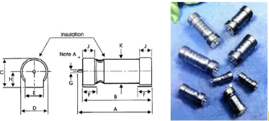
The historical SMTH approach used formed mounting tabs attached to an axial-style body. It illustrates one route to surface mounting, but should not be interpreted as evidence of current availability or compatibility with a modern automated reflow process.
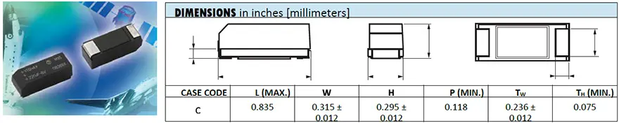
The M35 illustration shows a moulded surface-mount format described in the original article as containing an axial wet tantalum element connected to a leadframe. It is retained as construction history, not as a recommendation for a new design.
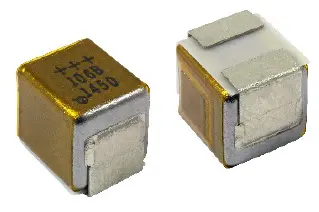
The Vishay T22 provides an example of a purpose-designed wet tantalum SMD package with a tantalum metal case and a glass-to-tantalum hermetic seal. Its product page identifies both tin-lead and 100% tin termination options. Select the appropriate ordering code and confirm the assembly requirements. [10]
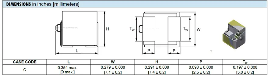
High-energy Assemblies and Capacitor Banks
Wet tantalum capacitors can be assembled in parallel to increase capacitance and current capability, or in series to support a higher bank voltage. A custom assembly can integrate mechanical restraint, insulation, interconnections, balancing components and protection suited to the equipment. [6, 9]
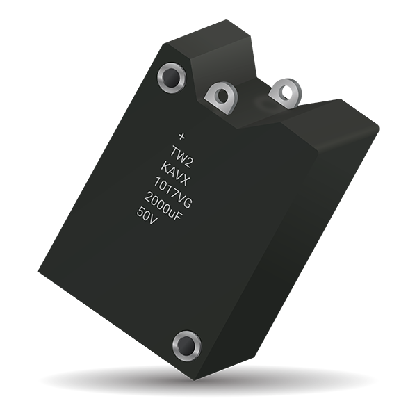
A parallel bank is not automatically current-balanced. Differences in ESR, wiring resistance, inductance and cooling affect ripple and pulse-current sharing. A failed element can also receive energy from the rest of the bank, so protective arrangements must consider the stored energy as well as the external source.
A series bank requires assessment of voltage distribution during charging, steady-state operation and transients. Leakage differences can affect the steady-state distribution, while capacitance and parasitic differences affect dynamic sharing. Balancing resistors increase standing power loss and do not, by themselves, solve every transient or reverse-voltage condition.
For catalogue arrays or custom modules, specify both the electrical duty and the mechanical environment. Include operating and fault voltages, energy, pulse current, repetition rate, thermal interfaces, allowable leakage, insulation, qualification, inspection and the required response to a failed element.
High-capacitance and Hybrid Cathode Designs
High-energy wet tantalum constructions use specialised cathode systems and larger active structures to support bulk energy storage and pulse applications. Some are described as hybrid capacitors, but the term does not specify one universal cathode chemistry or electrical characteristic. Use the manufacturer’s construction description and datasheet.
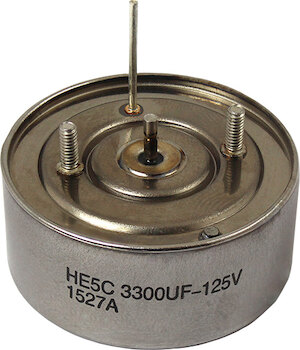
Vishay’s published product overview lists historical family ranges reaching 72 000 µF for HE5 and 79 000 µF for EP1. These figures demonstrate the scale of the technology; they are not evidence that the maximum capacitance and maximum family voltage occur together, or that every historical ordering code remains available. [9]
For an illustrative 72 000 µF capacitor charged to 25 V, Eq. (3) gives 22.5 J of stored energy. The useful energy is lower if the load cannot operate down to zero voltage, and further energy is lost in ESR and the power-conversion circuit.
Eq. (12) gives the ideal capacitive energy available between an initial voltage VH and a final voltage VL. It assumes a constant capacitance and excludes ESR, leakage and converter losses. Use capacitance in farads and voltages in volts to obtain Wuse in joules.
For a hold-up circuit, determine the required input energy from the load and converter efficiency, then apply the minimum effective capacitance and worst-case operating conditions. For a pulse circuit, also account for the immediate ESR voltage drop and the inductance of the capacitor, interconnections and switching path.
Specialised Medical Energy Storage
Implantable defibrillator energy storage uses specialised capacitor designs with requirements that differ from general-purpose industrial wet tantalum. Packaging, electrolyte containment, charge retention, pulse delivery and qualification must be addressed as part of the complete medical-device design.
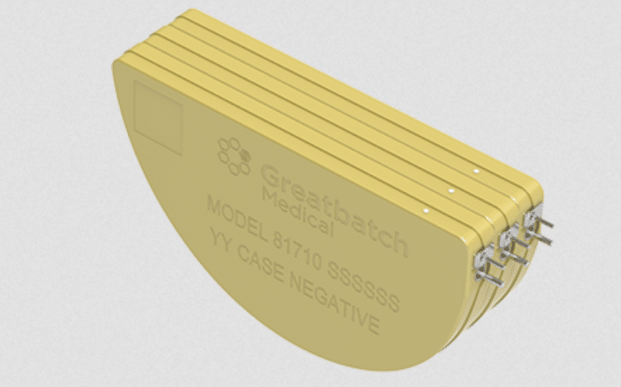
The original 400 µF, 250 V example corresponds mathematically to 12.5 J of stored energy. It is used here only to illustrate Eq. (3), not to specify an available medical capacitor. Package material, voltage capability and suitability for implantation must come from the approved component documentation.
A stable nominal ambient temperature does not remove the need to evaluate self-heating, charging duty, leakage over the storage interval, manufacturing variation and long-term containment. A general industrial product must not be substituted for a medically approved construction on the basis of nominal capacitance and voltage alone.
Examples of High-energy Package Styles
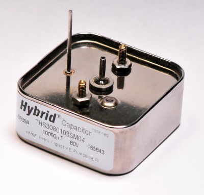
The following original illustrations show different high-energy wet tantalum package approaches. They are included to explain mechanical formats, not to establish current ordering codes or comparative performance. Electrical, thermal and qualification limits must be checked in the documentation for the exact product.
Design and Selection Checklist
Choose the capacitor from the required circuit behaviour and environmental conditions, then verify the exact orderable part number. Nominal capacitance, voltage and package outline are only the starting point; they do not establish electrical interchangeability, qualification or safe fault behaviour. [1, 2, 4, 6, 7]
Define the Application Class
- Power/SMPS input: assess source impedance, hot-plugging, inrush, supply transients, fault current and the consequence of a short circuit.
- Power/SMPS output: assess effective capacitance, ESR, impedance, ripple heating, load-step response and compatibility with the converter’s stability requirements.
- Timing, low-frequency signal and low-power functions: prioritise leakage, capacitance tolerance, dielectric absorption, temperature behaviour and any possibility of reverse bias.
- Hold-up and pulse energy: assess useful energy over the allowed voltage window, minimum effective capacitance, ESR drop, discharge current, repetition rate and charging conditions.
- Safety-related or high-reliability equipment: identify the required component qualification, screening, traceability, environmental evidence and system response to both parametric and catastrophic failure.
Compare the Datasheet Parameters
- Capacitance: nominal value, initial tolerance, measurement frequency and amplitude, temperature change, frequency roll-off and permitted change after qualification or endurance.
- Voltage: rated and category voltage, application derating, ripple peaks, transients, surge-test conditions and any explicitly permitted reverse excursion.
- ESR and impedance: guaranteed frequency and temperature conditions, typical curves, low-temperature behaviour, self-resonance and allowed post-test changes.
- Ripple and pulse current: reference frequency, ambient temperature, voltage utilisation, correction factors, permissible temperature rise and the installed cooling arrangement.
- Leakage: coefficient, minimum-current term, applied voltage, temperature, electrification time, moisture-state effects and post-test limits.
- Mechanical and assembly data: maximum dimensions, polarity marking, terminal finish, land pattern, soldering profile, moisture sensitivity, lead forming and mechanical restraint.
- Procurement: complete ordering code, screening option, qualification evidence, lifecycle status, change notices, traceability and approved alternatives.
Distinguish Qualification from Application Approval
A component qualification applies to a defined product, test programme and acceptance criteria. It does not prove that the part is suitable for every application in an industry or that it provides a specified system safety function. Similarly, a manufacturer’s reliability estimate is not a guarantee of service life. [4, 7, 8]
For a military or aerospace procurement route, identify the applicable specification or drawing, qualified source, screening level and ordering option. A commercial catalogue description and a procurement-controlled part number may have different acceptance requirements even when the nominal capacitance and package are similar. [4, 7]
Endurance-test duration is a qualification condition, not automatically the expected application lifetime. Do not transfer a lifetime-doubling rule or an acceleration factor between wet, MnO2 and polymer products without a model supported for the selected construction.
Choose Catalogue or Custom Construction
A catalogue part is generally preferable when its guaranteed electrical and mechanical limits satisfy the application. It simplifies documentation and replacement, but still requires confirmation that the exact code is orderable and supported.
A custom part or assembly may be justified by energy, geometry, mounting, environmental or interconnection requirements that catalogue parts cannot meet. Define measurable acceptance criteria rather than requesting only a nominal capacitance, voltage and enclosure size.
- Specify the complete operating waveform, including charge, ripple, discharge and fault events.
- Define electrical limits at the temperature extremes and after the required environmental and endurance tests.
- Define insulation, mechanical restraint, thermal interfaces, terminal loading and inspection access.
- Agree the screening, traceability, documentation, change-control and lifecycle arrangements.
- Evaluate whether the custom assembly introduces a single-source dependency that requires spare-stock or redesign planning.
Validate the Installed Design
Measure the actual terminal waveform and local temperature under worst-case normal operation and relevant abnormal conditions. Include startup, shutdown, rapid restart, supply tolerance, load steps, hot-plugging and cooling variations. Use test equipment and fixtures that do not introduce unintended current or reverse-voltage stress.
Record the design margins, model assumptions, measurement conditions and approved alternatives. The selection is complete only when the installed component meets the circuit requirements, the assembly process and the applicable procurement and safety constraints.
Conclusion
Tantalum and niobium-based capacitors provide compact capacitance through porous anodes and thin oxide dielectrics, but their cathode systems determine important differences in ESR, environmental behaviour and fault response. MnO2 tantalum, conductive-polymer tantalum, NbO and wet tantalum should therefore be treated as distinct selection options rather than interchangeable versions of the same component.
Choose the technology from the circuit’s required capacitance, impedance, leakage, energy and thermal performance. Then verify the exact part number against voltage and temperature limits, ripple and transient conditions, assembly requirements, qualification and sourcing. Self-healing and self-arresting mechanisms can reduce the consequences of local dielectric defects, but neither replaces appropriate circuit protection or validation of the installed design.
FAQ
These answers summarise the main technology differences and the checks required when selecting or replacing a capacitor.
Tantalum capacitors use a tantalum anode and a tantalum pentoxide dielectric. Niobium oxide capacitors use a conductive NbO anode and a niobium pentoxide dielectric, normally with a manganese dioxide cathode system. Their voltage range, ESR, leakage and fault behaviour differ. A matching package does not establish electrical interchangeability or equivalent qualification.
Conductive-polymer tantalum generally provides lower ESR, better high-frequency capacitance retention and reduced ignition risk compared with manganese dioxide tantalum. Manganese dioxide remains useful where its leakage limits, environmental performance or qualified procurement route suit the requirement. Compare the exact series, including humidity capability, temperature limits, screening and converter stability, rather than selecting by cathode material alone.
There is no universal derating percentage for every tantalum capacitor. Manganese dioxide types in low-impedance power circuits commonly require substantial voltage margin and control of inrush current. Polymer types generally need less margin. Follow the selected series guidance, include ripple and transients, and apply its temperature-dependent category-voltage limit separately from the application guard band.
Tantalum capacitors are polarised and should not be designed for continuous reverse operation. Some series permit small reverse transients under specified voltage, temperature, duration and repetition conditions. Those allowances are not transferable between solid, polymer and wet constructions. If the selected product does not explicitly permit the expected excursion, prevent it or choose a suitable non-polar technology.
Self-healing can isolate a local dielectric defect, while NbO capacitors have an additional self-arresting mechanism that restricts fault current. Neither mechanism guarantees complete recovery, unchanged parameters or immunity to a short circuit. Available circuit energy, temperature and the defect itself influence the outcome. Appropriate voltage margin, current control and system-level fault protection remain necessary.
Wet tantalum capacitors are useful for compact energy storage, hold-up and selected pulse-power applications where low leakage and environmental performance justify their cost. Cathode design, case construction and seals strongly affect performance. Check low-temperature capacitance and impedance, ripple heating, discharge duty and reverse-transient limits. A general wet tantalum description does not establish suitability for a specialised medical application.
CV/g is a powder-specific charge measure expressed in microfarad-volts per gram. It uses the capacitance of a test anode and its formation voltage under defined processing and measurement conditions. It is not the energy density or guaranteed capacitance density of a finished capacitor. Formation margin, cathode coverage, anode geometry and package overhead also determine finished performance.
How to Select and Validate a Tantalum or Niobium Capacitor
Use this procedure to connect the circuit requirements to an orderable component and a documented validation plan.
Select a suitable construction, verify its limits and validate the component in the installed circuit.
- Define the operating conditions
Record the required capacitance, operating-voltage range, ripple spectrum, transients, temperature, humidity and mechanical environment. Identify whether the function is filtering, timing, hold-up or pulse energy storage, and define the consequences of capacitor failure.
- Choose the construction
Compare manganese dioxide tantalum, conductive-polymer tantalum, NbO and wet tantalum using effective capacitance, ESR, leakage, temperature behaviour and fault response. Check the available packages and sourcing options rather than assuming that a common footprint establishes interchangeability.
- Check voltage and current margins
Apply the selected series voltage derating and category-voltage limits. Include ripple peaks, startup, shutdown and abnormal events. Check polarity, surge conditions, RMS ripple heating and any pulse duty, and define the required current control or protection.
- Verify assembly and procurement requirements
Confirm the complete ordering code, dimensions, termination finish, land pattern, soldering limits, moisture handling and mechanical support. Verify qualification, screening, traceability and lifecycle status. For custom parts, agree measurable electrical, environmental and mechanical acceptance criteria.
- Measure and validate the installed component
Match the datasheet measurement conditions when checking capacitance, ESR and leakage. Measure terminal voltage, current and local temperature in the installed circuit, including relevant transients and temperature extremes. Verify converter stability and useful stored energy where applicable.
- Document the approved selection
Record the design margins, test conditions, protection strategy, qualification evidence and approved alternatives. Retain the supporting datasheet revision and model assumptions. Reassess the selection when the supplier changes the product or when the circuit or assembly process changes.
Further Reading
The following articles provide additional context on the technology’s development, alternative constructions and the calculations used in component selection.
- Tantalum Capacitor History — explains the development from wet tantalum to solid MnO2 and conductive-polymer cathode systems.
- Electrolytic Capacitors — provides the broader construction and measurement principles shared by oxide-dielectric capacitors.
- Aluminum Electrolytic Capacitors — supports comparison with wet, polymer and hybrid aluminium alternatives for filtering and energy storage.
- Capacitance and its Calculation — explains charge, capacitance, series and parallel connections, and the assumptions behind ideal calculations.
References
The numbered documents support the construction principles, application guidance and product-specific examples cited in the text. Series datasheets and procurement specifications take precedence over general technology comparisons.
- KYOCERA AVX, Technical Summary and Application Guidelines: Polymer, Tantalum and Niobium Oxide Capacitors, KYOCERA AVX, publication year not stated; accessed 3 November 2026.
- S. Zedníček, J. Petržílek, P. Vanšura, M. Weaver and C. Reynolds, Conductive Polymer Capacitors: Basic Guidelines, KYOCERA AVX, publication year not stated; accessed 3 November 2026.
- Philip Lessner, James Q. Chen and Hideaki Sato, Tantalum Capacitor History Part 1: Invention of the Solid Tantalum Capacitor, Phil Lessner, 23 December 2024.
- KEMET, KEMET Organic Capacitor: T540/T541 High Reliability Series, Polymer Electrolytic, 2.5–63 V DC, YAGEO Group, document T2077_T540-541, revision 9 September 2026.
- T. Zedníček, Tantalum Polymer and Niobium Oxide Capacitors, AVX technical paper, publication year not stated in the document; accessed 3 November 2026. Used for historical development and fault-mechanism context.
- Vishay, Wet Electrolyte Tantalum Capacitors: An Introduction to the Basics, Vishay Intertechnology, document 40021, revision 6 August 2024.
- Vishay, DLA 93026: Wet Tantalum Capacitors, Vishay Intertechnology, document 40136, revision 23 March 2022.
- KYOCERA AVX, OxiCap NOS Series, KYOCERA AVX product information, publication year not stated; accessed 3 November 2026.
- Vishay, Tantalum Capacitors, Vishay Intertechnology, document 49657, 2018. Used for historical product-range context.
- Vishay, T22: Wet Tantalum SMD Capacitors, Tantalum Metal Case with Glass-to-Tantalum Hermetic Seal, Vishay Intertechnology product information, publication year not stated; accessed 3 November 2026.
Latest technical review and revision: 3 November 2026.