Passive Components Blog
No Result
View All Result
  • Home
  • NewsFilter
    • All
    • Aerospace & Defence
    • Antenna
    • Applications
    • Automotive
    • Capacitors
    • Circuit Protection Devices
    • electro-mechanical news
    • Filters
    • Fuses
    • Inductors
    • Industrial
    • Integrated Passives
    • inter-connect news
    • Market & Supply Chain
    • Market Insights
    • Medical
    • Modelling and Simulation
    • New Materials & Supply
    • New Technologies
    • Non-linear Passives
    • Oscillators
    • Passive Sensors News
    • Resistors
    • RF & Microwave
    • Telecommunication
    • Weekly Digest

    TDK Extends SMT Gate Drive Transformers to 1000 V

    Non-Linear MLCC Class II Capacitor Measurements Challenges

    Researchers Demonstrated HfO Anti-Ferroelectric Flexible Capacitors

    Connector Industry Achieves Double-Digit Growth

    Stackpole Unveils Metal Element High Current Chip Jumpers

    Common Mistakes in Flyback Transformer Specs

    Vishay Releases Miniature SMD Trimmers for Harsh Environments

    Würth Elektronik Releases Push-Button and Main Switches

    Littelfuse Unveils High-Precision TMR Angle Magnetic Sensors

    Trending Tags

    • Ripple Current
    • RF
    • Leakage Current
    • Tantalum vs Ceramic
    • Snubber
    • Low ESR
    • Feedthrough
    • Derating
    • Dielectric Constant
    • New Products
    • Market Reports
  • VideoFilter
    • All
    • Antenna videos
    • Capacitor videos
    • Circuit Protection Video
    • Filter videos
    • Fuse videos
    • Inductor videos
    • Inter-Connect Video
    • Non-linear passives videos
    • Oscillator videos
    • Passive sensors videos
    • Resistor videos

    Non-Linear MLCC Class II Capacitor Measurements Challenges

    Percolation Phenomenon and Reliability of Molded Power Inductors in DC/DC converters

    Root Causes and Effects of DC Bias and AC in Ceramic Capacitors

    How to Calculate the Output Capacitor for a Switching Power Supply

    Switched Capacitor Converter Explained

    Understanding Inductor Dot Markings and Their Application in LTspice

    Accelerating Full Bridge LLC Resonant Converter Design with Frenetic AI

    Understanding Switched Capacitor Converters

    Coupled Inductors Circuit Model and Examples of its Applications

    Trending Tags

    • Capacitors explained
    • Inductors explained
    • Resistors explained
    • Filters explained
    • Application Video Guidelines
    • EMC
    • New Products
    • Ripple Current
    • Simulation
    • Tantalum vs Ceramic
  • Knowledge Blog
  • Suppliers
    • Who is Who
  • Events
No Result
View All Result
Passive Components Blog
No Result
View All Result

What Are Bias Filter and Self-Bias Networks?

9.11.2023
Reading Time: 4 mins read
A A

This article based on Knowles Precision Devices blog introduces bias filter networks and self-bias networks – the two types of biasing components developed by Knowles Precision Devices for use in high-frequency microwave and RF applications.

What Are Bias Filter Networks?

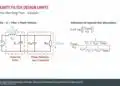
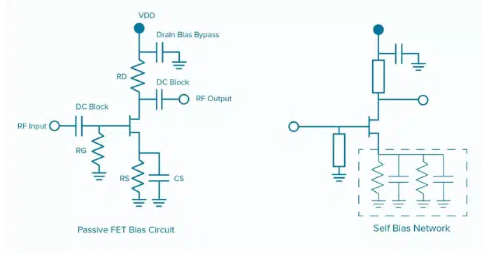
Bias filter networks in RF amplifiers refer to specific arrangements of passive components like resistors, capacitors, and inductors that provide a stable DC bias voltage or current to the active devices in the amplifier. 

RelatedPosts

Knowles Unveils High-Performance Safety-Certified MLCC Capacitors

Knowles Releases Inductors for Mission-Critical RF Applications

Learn How Supercapacitors Enhance Power System in Knowles eBook

They have three main functions:

  • Biasing: Providing the required DC voltage/current to the transistors to keep them operating in their optimal region.
  • Filtering: Using capacitors and inductors to prevent RF signals from flowing back into the DC supply or other circuit sections, avoiding interference and instability.
  • Decoupling: Isolating different amplifier stages to prevent their performances from impacting each other, which is important in multi-stage amplifiers

Bias filter networks play a crucial role in ensuring RF amplifiers operate efficiently, maintain linearity, and minimize noise/interference.

What Are Self-Bias Networks?

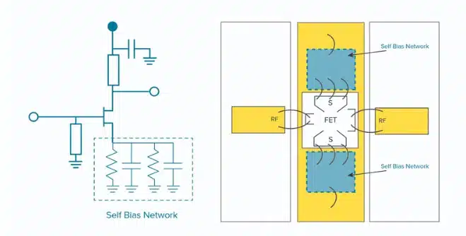
Self-bias networks in RF/microwave circuits are configurations designed to automatically set the DC bias point of active devices like transistors without requiring an external bias supply. They consist of resistors and capacitors connected to the device’s terminals in a voltage divider configuration to provide the bias voltage, while blocking DC signals.

The main advantage of self-bias networks is they automatically adjust the bias point based on factors like device characteristics and temperature to maintain consistent circuit performance. They simplify design and reduce components needed.

Figure 1. A Passive FET Bias Network and a Self Bias Network product used on the source leg of a FET.

How Bias Filter Networks and Self-Bias Networks Work

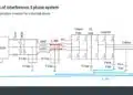
Bias filter networks filter noise from DC supplies and reduce RF feedback in high-frequency applications like wireless communications. They combine high-permittivity dielectrics and thin-film processing to filter noise when transmitting DC voltage from point A to B in a circuit.

Bias filter networks should be used in applications that require filtering of noise and isolation of RF signals from DC bias lines, such as:

  • Gate biasing for FETs and MMICs
  • Varactor control lines in VCOs, frequency synthesizers, and PLLs
  • Mixed signal modules with both analog and high-speed digital signals
  • Cascaded high-gain amplifier modules sharing a common gate bias

Self-bias networks integrate decoupling capacitors and user-selectable bias resistors to optimize bias currents for amplifiers, such as GaAs and GaN FET amplifiers. They use high-permittivity ceramics and thin-film resistors to provide adjustable bias resistance and improve gain flatness/stability in FETs.

Figure 2. Custom application of a self-bias network, implemented in a hybrid assembly, with a self-bias network attached source connections of the MMIC.

Integrating Bias Filter Networks and Self-Bias Networks from Knowles Precision Devices

Knowles leverages specialized expertise with high-permittivity materials and thin-film processing o develop customized bias filter and self-bias networks that provide critical biasing, filtering and isolation functions in high-frequency microwave and RF applications. With a broad range of solutions, Knowles bias filter networks are designed to filter RF signals from bias and control lines from 10 MHz to 40 GHz.

With bias filter and self-bias networks from Knowles, engineers:

  • Simplify assembly by integrating multiple discreet components into one surface-mountable package
  • Reduce size, weight and power consumption
  • Effectively filter noise and optimize biasing
  • Maximize isolation when mounting directly on a ground plane

Related

Source: Knowles Precision Devices

Recent Posts

KYOCERA AVX Releases 600MHz Band71 Compact SAW Duplexer

30.7.2025
9

Murata Releases First High-Frequency XBAR Filter for Next-Gen Networks

8.7.2025
31

TDK Introduces High Current 80VDC Board-Mount EMI Filters

2.7.2025
42

Role of High-Q Ceramic Filters to Overcome GNSS Jamming

19.6.2025
28

Bourns Introduces 1206 Multilayer Common Mode Filters

16.6.2025
11

Bourns Releases New SMD Line Filter for Enhanced EMI Suppression

4.6.2025
23

TDK Expands 3-terminal Automotive SMD Chip Filters to 35V

4.6.2025
23

Kyocera Introducing SAW Filters for Implantable Medical and AED Applications

15.4.2025
30

Bourns Releases Automotive Grade Line Filters

1.4.2025
27

KYOCERA AVX Extends Small, High-Power, Thin-Film Band-Pass Filters

29.1.2025
38

Upcoming Events

Aug 27
17:00 - 18:00 CEST

Capacitor Assemblies for High-Power Circuit Designs

Sep 3
15:30 - 17:30 CEST

How to Choose Your Magnetic Supplier

Sep 16
17:00 - 18:00 CEST

EMI Shielding Challenges

Sep 22
September 22 @ 13:00 - September 25 @ 15:15 EDT

Pre Cap Visual Inspection per Mil-Std-883 (TM 2017)

Sep 30
September 30 @ 12:00 - October 2 @ 14:00 EDT

MIL-Std-883 TM 2010

View Calendar

Popular Posts

  • Buck Converter Design and Calculation

    0 shares
    Share 0 Tweet 0
  • Boost Converter Design and Calculation

    0 shares
    Share 0 Tweet 0
  • Flyback Converter Design and Calculation

    0 shares
    Share 0 Tweet 0
  • LLC Resonant Converter Design and Calculation

    0 shares
    Share 0 Tweet 0
  • What is a Dielectric Constant and DF of Plastic Materials?

    4 shares
    Share 4 Tweet 0
  • Ripple Current and its Effects on the Performance of Capacitors

    3 shares
    Share 3 Tweet 0
  • Dual Active Bridge (DAB) Topology Explained

    0 shares
    Share 0 Tweet 0
  • How to Design an Inductor

    0 shares
    Share 0 Tweet 0
  • Core Materials, Permeability and Their Losses

    0 shares
    Share 0 Tweet 0
  • MLCC Case Sizes Standards Explained

    0 shares
    Share 0 Tweet 0

Newsletter Subscription


Passive Components Blog

© EPCI - Leading Passive Components Educational and Information Site

  • Home
  • Privacy Policy
  • EPCI Membership & Advertisement
  • About

No Result
View All Result
  • Home
  • Knowledge Blog
  • Premium Suppliers

© EPCI - Leading Passive Components Educational and Information Site

This website uses cookies. By continuing to use this website you are giving consent to cookies being used. Visit our Privacy and Cookie Policy.
Go to mobile version