











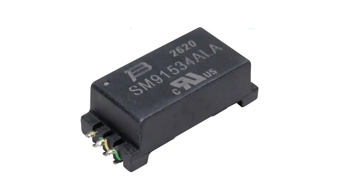
Bourns has introduced the SM91534ALA, an automotive-grade battery-management-system (BMS) signal transformer for high-voltage isolation and noise rejection in electric and hybrid vehicle battery architectures, as well as stationary energy-storage battery packs.
The single-channel BMS signal transformer combines reinforced insulation with integrated common-mode choke functionality, addressing two key requirements of isolated BMS communication links: safety separation and resilience to conducted noise.
Key features and benefits
- Reinforced insulation for high-voltage BMS domains: The SM91534ALA is specified for up to 1,500 VDC working voltage and a 6,400 VDC Hi-Pot test level, supporting galvanic separation between battery-stack circuitry and lower-voltage control electronics.
- Integrated common-mode choke function: Combining the signal transformer and common-mode choke function can reduce the need for separate magnetic components in the communication path. In practical terms, common-mode filtering helps reject noise that appears in the same direction on both conductors, a relevant concern around high-voltage switching systems.
- Automotive qualification: Bourns states AEC-Q200 compliance and an operating-temperature range from -40 °C to +125 °C, making the part suitable for demanding automotive electronic environments.
- Automated pin termination: The component uses auto pin termination, which Bourns positions as an alternative to manual versions for automated assembly, quality consistency, and manufacturing cost control.
- High-voltage insulation geometry: Creepage and clearance distances exceed 16.6 mm. These physical PCB-interface distances are important because they help maintain insulation integrity under the stated pollution degree, overvoltage category, and altitude conditions.
- Compliance support: The model is stated to comply with RoHS Directive 2015/863 requirements.
Technical highlights
| Parameter | Bourns SM91534ALA |
|---|---|
| Component type | Single-channel BMS signal transformer with integrated common-mode choke functionality |
| Inductance | 150 to 450 µH |
| Working voltage | Up to 1,500 VDC |
| Hi-Pot test voltage | 6,400 VDC |
| Impulse withstand | 12 kV, 1.2/50 µs |
| Insulation | Reinforced insulation |
| Creepage distance | Greater than 16.6 mm |
| Clearance distance | Greater than 16.6 mm |
| Operating temperature | -40 °C to +125 °C |
| Package dimensions | 31.5 × 12.5 × 9.5 mm |
| Qualification | AEC-Q200 compliant; UL Recognized, file E515965, per UL 62368-1 |
| Environmental compliance | RoHS Directive 2015/863 compliant |
Bourns specifies reinforced insulation in accordance with IEC 62477-1:2022 and IEC 62368-1:2018. The stated clearance performance applies to Pollution Degree 2, Material Group CTI I, Overvoltage Category II, and altitudes up to 5,000 m.
The 12 kV impulse-voltage rating is specified using a 1.2/50 µs waveform, a standard surge representation used when assessing insulation coordination. Final system-level compliance still depends on the complete PCB layout, spacing, enclosure, contamination environment, and the applicable end-product standard.
Typical applications
- Battery-management systems in hybrid and electric powertrain systems
- Isolated communication and sensing links within high-voltage battery packs
- Energy-storage battery packs incorporating battery-management systems
- BMS architectures where transformer isolation and common-mode noise suppression are both required
Application fit
High-voltage battery packs place low-voltage monitoring, balancing, and control electronics close to conductors and switching systems that can generate substantial common-mode disturbances. A transformer with an integrated choke function is intended to preserve signal transmission across an isolation barrier while helping reduce the noise coupled onto the communication pair.
For BMS engineers, this makes the SM91534ALA a potential fit where the insulation system must accommodate a 1,500 VDC working-voltage requirement and where the magnetic component must operate across the automotive -40 °C to +125 °C range. Procurement teams should verify the required isolation class, magnetic characteristics, approved footprint, qualification documentation, and supply status according to the current manufacturer datasheet.
Design-in notes for engineers
- Check the insulation system as a whole: The transformer’s specified creepage and clearance figures do not replace PCB creepage, clearance, coating, connector, enclosure, or contamination analysis.
- Confirm the operating-voltage definition: Match the 1,500 VDC working-voltage rating to the actual continuous voltage stress across the isolation barrier, including foreseeable fault and transient conditions.
- Review signal-interface requirements: Confirm the required inductance range, communication protocol, transformer drive conditions, termination network, and allowable signal distortion using the manufacturer datasheet and the BMS IC supplier’s reference design.
- Treat common-mode performance as system dependent: Integrated choke functionality can help reduce conducted common-mode interference, but final EMC results also depend on cable routing, return-current paths, grounding strategy, PCB stack-up, and external filtering.
- Assess assembly compatibility: Validate pin geometry, hole pattern, board thickness, solder process, component height, and automated insertion requirements before releasing the footprint.
- Use qualification data for release: AEC-Q200 compliance supports automotive component qualification, but does not by itself qualify the completed battery pack or vehicle subsystem.
Further reading
- Bourns Releases Automotive BMS Signal Transformer
- Bourns Releases Automotive BMS Signal Transformer with Integrated Common Mode Chokes
- Dual-Mode Chokes Expand Inverters Capabilities
- Bourns Releases Automotive Planar Signal BMS Transformer
Source
This article is based on the manufacturer’s product release for the Bourns SM91534ALA BMS signal transformer. Engineers should consult the current manufacturer datasheet and supporting documentation for final component qualification, circuit design, and production release.












