











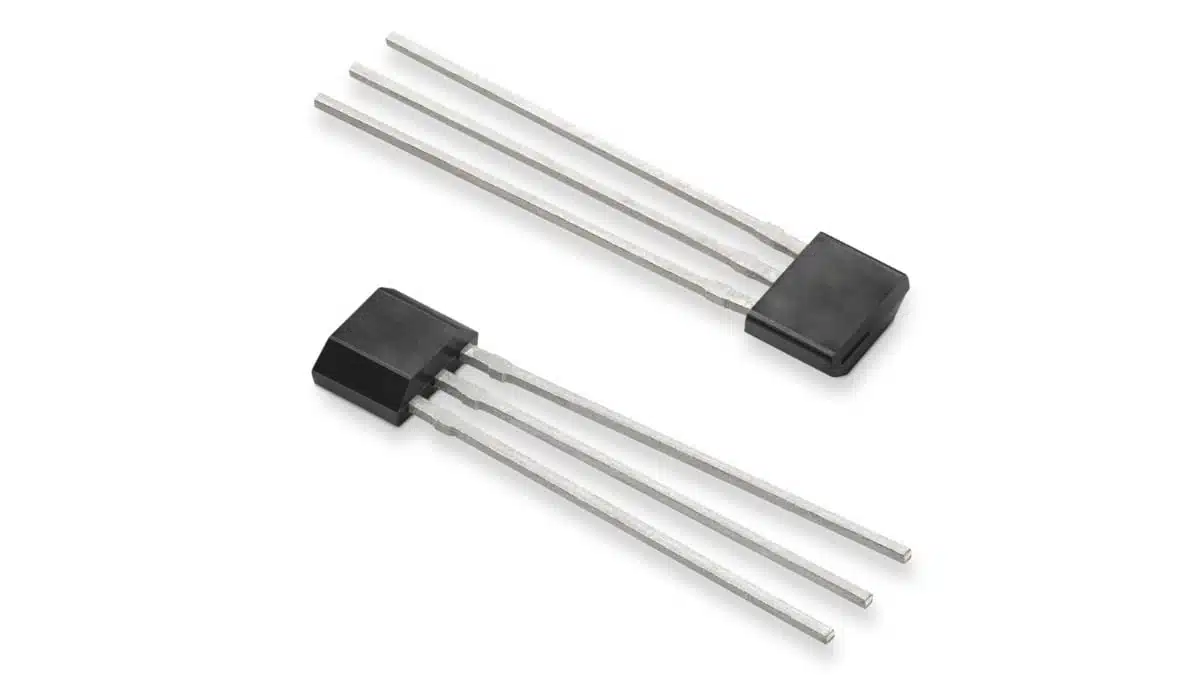
Littelfuse has expanded its TX00 tunnelling magnetoresistance (TMR) magnetic-switch family with the TX00AT314AMA, a digital omnipolar switch in a leaded TO-92-3 package.
The Littelfuse TMR switch new option brings the TX00 platform to through-hole assembly and prototype-oriented builds while retaining the manufacturer-stated low-current, high-sensitivity magnetic-switch characteristics.
What is new
The TX00AT314AMA is a new package and sourcing option within the Littelfuse TX00 TMR Switch family. Littelfuse states that it has the same electrical and magnetic characteristics as the surface-mount TX00AS314TRA, but uses a leaded TO-92 package and has South Korea country of origin.
The change is relevant where a through-hole sensor is preferable for early prototypes, low-to-medium-volume assembly, serviceable boards, or existing PCB platforms that do not use reflow soldering for the sensor position.
Key features and benefits
- Leaded TO-92-3 package supports through-hole PCB assembly and straightforward prototype integration.
- Omnipolar operation detects either north or south magnetic poles, reducing dependence on magnet-pole orientation during mechanical assembly.
- TMR sensing element with CMOS signal conditioning integrates a voltage generator, amplifier, comparator, Schmitt trigger and push-pull output in one package.
- X-axis magnetic sensing responds to a magnetic field parallel to the sensor surface; magnet direction and sensor orientation therefore remain key mechanical design inputs.
- Typical 1.5 µA supply current supports continuously powered, battery-operated sensing functions where quiescent-current budget matters.
- Up to 1 kHz switching frequency supports applications including rotational detection, speed sensing, position indication and proximity switching.
- Specified high sensitivity of approximately 14 Gauss may permit use of relatively small magnets, but actual switching distance depends on the magnet, air gap, orientation, nearby ferromagnetic material and production tolerances.
- South Korea country of origin adds a sourcing option for organisations managing country-of-origin, tariff or supply-chain-diversification requirements.
Technical highlights
| Parameter | Published information |
|---|---|
| Product | Littelfuse TX00AT314AMA |
| Component type | Digital omnipolar TMR magnetic switch |
| Package | TO-92-3, leaded |
| Sensing direction | X-axis |
| Pole response | North and south magnetic poles |
| Supply current | 1.5 µA typical |
| Switching frequency | Up to 1 kHz |
| Sensitivity | Approximately 14 Gauss |
| Output | CMOS push-pull |
| Noise-rejection function | Schmitt-trigger hysteresis |
| Product status | Active |
The product page identifies the device as a digital magnetic switch rather than a linear field sensor. It provides a logic-level switching output when the applied field crosses its operate and release thresholds, with hysteresis intended to prevent repeated output transitions around the switching point.
The available product page links to the TX00AS314TRA datasheet. For final selection, engineers should confirm that document’s current ratings, supply-voltage range, magnetic operate and release thresholds, hysteresis, output loading, timing, temperature limits, package drawing and absolute maximum ratings against the intended TX00AT314AMA implementation.
Typical applications
Littelfuse identifies the following application areas for the TX00AT314AMA:
- Proximity switches
- Position sensing
- Speed sensing
- Utility meters for gas, water and heat
- Low-power electronic systems
- Building and home automation equipment
- Appliances and power tools
- Battery-powered IoT and wearable equipment
For a utility-meter tamper or cover-detection circuit, omnipolar sensing can simplify magnet installation because either magnet pole can activate the switch. In a rotating-speed application, the 1 kHz maximum switching-frequency specification must be checked against the highest rotational speed and the number of magnetic transitions per revolution.
Application fit
| Design situation | Practical relevance |
|---|---|
| Through-hole prototype or legacy PCB | The TO-92-3 format avoids the need for a SOT-23-3 footprint and reflow process at the sensor location. |
| Battery-powered always-on sensor | The stated 1.5 µA typical current should be included in the full sleep-mode and battery-life budget. |
| Lid, cover or tamper detection | Omnipolar response can reduce magnet-polarity assembly constraints. |
| Magnet-based speed sensing | Confirm that the total switching-event rate remains within the stated 1 kHz capability. |
| Noisy electrical environment | The integrated Schmitt trigger provides hysteresis, but conducted, radiated and transient immunity still require system-level validation. |
| Supply-chain diversification | Country of origin may support procurement requirements, but availability and approved-source status should be confirmed directly with authorised channels. |
Design-in notes for engineers
- Validate the magnetics mechanically. Establish the complete tolerance stack-up for magnet grade, size, placement, sensor position, enclosure wall, air gap and any steel or magnetic material near the sensing path.
- Use operate and release limits, not only a nominal sensitivity figure. The approximate 14 Gauss figure in the announcement is not a substitute for the guaranteed magnetic thresholds in the current datasheet.
- Check field direction. The sensor uses X-axis sensing, so a magnetic arrangement developed for a Hall sensor or a differently oriented TMR package may require mechanical redesign.
- Assess switching speed at worst case. Calculate transitions per second from the maximum movement or shaft speed, including every magnetic pole or target feature that produces a field crossing.
- Confirm the output interface. Validate supply voltage, CMOS push-pull output compatibility, logic thresholds, loading, start-up state and any protection needed at cable-connected inputs.
- Treat hysteresis as a switching-stability feature, not complete EMC protection. Test the installed circuit for supply transients, ESD, fast switching edges, conducted interference and radiated susceptibility.
- Review the assembly process. Verify the TO-92 lead form, hole pitch, board thickness, soldering profile, clearance to neighbouring components and enclosure stress after assembly.
- Confirm production documentation. The manufacturer’s announcement does not specify all limits required for release; the current Littelfuse datasheet and package documentation should control schematic, PCB-layout and qualification decisions.
Further reading
- Littelfuse Unveils Ultra-Low-Power TMR Magnetic Switches
- Hall Effect Magnetic Positioning Sensors Explained
- Littelfuse Unveils High-Precision TMR Angle Magnetic Sensors
- The Difference Between Inductive Proximity, Displacement, and Eddy Current Sensors
Source
This article is based on the Littelfuse press release and product information for the TX00AT314AMA. Engineers should consult the current manufacturer datasheet, package drawing and applicable qualification documentation before final component qualification and design release.












