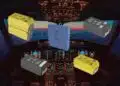





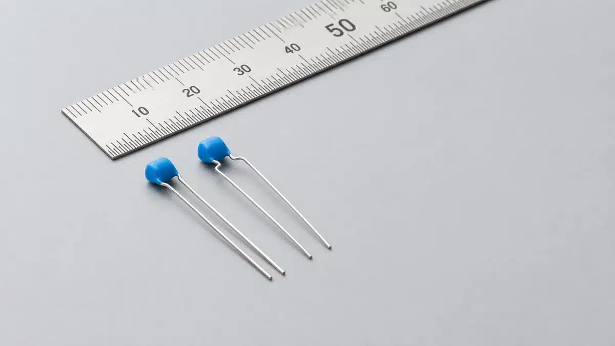
Murata has expanded its lead-type multilayer ceramic capacitor portfolio with new 100 Vdc, 10 µF devices aimed at 48 V power architectures.
The new Murata RCE and RDE series parts combine high capacitance with a resin-molded, leaded MLCC construction intended to reduce stress on the ceramic body in vibration-, flexure-, and thermally demanding assemblies.
Key features and benefits
- 100 Vdc rated voltage and 10 µF capacitance address the growing need for higher-voltage bulk and local decoupling capacitance in 48 V electrical systems.
- Lead-type MLCC construction places a ceramic capacitor element inside a resin-molded package with attached lead wires, rather than soldering a chip MLCC directly to the PCB.
- Stress relief at the connection can reduce mechanical load transferred to the ceramic element from PCB bending, vibration, and differential thermal expansion.
- Compact package for the electrical rating: Murata states that the component achieves the smallest volume and height among lead-type MLCCs specified at 100 Vdc and 10 µF, based on its research as of August 26, 2026.
- Higher capacitance at 100 V: the new device increases Murata’s maximum capacitance in its 100 V lead-type MLCC range from 4.7 µF to 10 µF.
- Series allocation by market: RCE is positioned for automotive powertrain and safety equipment, while RDE targets consumer and industrial equipment.
The product is particularly relevant where conventional board-mounted MLCCs are exposed to flexure or vibration, or where the capacitor must be located away from the main PCB. For background on ceramic construction and use cases, see the MLCC and Ceramic Capacitors overview.
Technical highlights
| Parameter | Murata specification |
|---|---|
| Part numbers | RCEC72A106K3*; RDEC72A106K3* |
| Capacitance | 10 µF |
| Capacitance tolerance | ±10% |
| Rated voltage | 100 Vdc |
| Temperature characteristic | X7S |
| Operating temperature range | -55 °C to +125 °C |
| Dimensions, L × T × W × W1 | 5.5 mm × 4.0 mm × 5.0 mm × 7.5 mm |
| Production status | Mass production began in August 2026 |
The X7S dielectric designation indicates a Class II ceramic capacitor designed for a -55 °C to +125 °C operating range. However, as with other high-capacitance Class II MLCCs, the effective capacitance in a circuit can vary with DC bias, temperature, AC signal level, ageing, and mechanical conditions; designers should evaluate the actual in-circuit capacitance rather than relying only on the nominal 10 µF rating. The temperature, bias and ageing behaviour of MLCCs is therefore an important selection consideration.
Typical applications
Murata identifies the new lead-type capacitors for applications moving toward 48 V power systems.
- Automotive electric power steering systems
- Brake-system electronics
- Electric water pumps and auxiliary drives
- Automotive powertrain and safety modules
- 48 V consumer and industrial power electronics
- Humanoid robots and other higher-power robotic equipment
- Off-board capacitor locations where direct surface mounting is impractical
In automotive platforms, a 48 V rail can reduce current for a given power level compared with a 12 V system, but it also raises voltage-rating and transient-margin requirements for local energy storage, filtering, and decoupling networks. The wider passive-component context is covered in Passive Automotive Electronics for 48V Systems and V2X.
Application fit
| Design situation | Why a lead-type 100 V MLCC may fit |
|---|---|
| PCB subject to bending or assembly stress | Lead wires can mechanically decouple the ceramic body from board flexure. |
| Vibration-exposed module | The molded leaded structure is intended to reduce mechanical stress transfer to the capacitor. |
| Capacitor mounted away from the PCB | Leaded construction enables placement where a conventional chip capacitor cannot be directly surface-mounted. |
| 48 V rail decoupling or filtering | The 100 Vdc rating provides a higher nominal voltage class than 50 V parts for a 48 V architecture. |
| High-temperature automotive electronics | The stated operating range extends to +125 °C. |
Design-in notes for engineers
- Validate operating voltage margin: A 48 V nominal rail can experience switching, load-dump, inductive, and cable-related transient conditions. Confirm the complete voltage waveform, including abnormal operating cases, against the manufacturer’s current application documentation.
- Check effective capacitance under bias: The nominal 10 µF value should be verified at the intended DC voltage and temperature, especially if the capacitor supports regulator stability, hold-up, damping, or an EMC filter corner frequency.
- Review ripple-current and self-heating limits: Murata’s press release does not provide ripple-current, ESR, impedance, or permissible temperature-rise data. Confirm these parameters according to the manufacturer datasheet before final design release.
- Use the leaded structure intentionally: The mechanical benefit comes from the lead-wire and resin-molded architecture. Define lead forming, soldering, mounting orientation, clearance, and vibration constraints according to the manufacturer’s mounting guidance.
- Consider parasitics in fast-switching circuits: Leaded capacitors generally introduce more connection inductance than a directly mounted chip MLCC. For high-frequency switching edges, placement and parallel local MLCCs may still determine the decoupling performance.
- Do not infer automotive qualification from series positioning alone: The RCE series is stated for automotive powertrain and safety equipment, but the press release does not specify an AEC-Q200 qualification claim for these exact part numbers. Confirm qualification, screening, traceability, and approved-grade requirements with Murata for the intended program.
- Check supply and approved-source status: For production programs, verify exact ordering suffixes, availability, packaging, lifecycle status, and PPAP or customer-specific requirements directly with the manufacturer.
Further reading
- MLCC and Ceramic Capacitors
- Temperature, Bias and Ageing Impact to MLCC Ceramic Capacitor Stability
- MLCC Capacitors in Electrical Vehicles
- Passive Automotive Electronics for 48V Systems and V2X
Source
This article is based on Murata Manufacturing’s product press release announcing the RCE and RDE 100 Vdc, 10 µF lead-type MLCCs. Engineers should consult the current manufacturer datasheet, product finder entry, mounting documentation, and qualification information before final component selection and design release.