Passive Components Blog
No Result
View All Result
  • Home
  • NewsFilter
    • All
    • Aerospace & Defence
    • Antenna
    • Applications
    • Automotive
    • Capacitors
    • Circuit Protection Devices
    • electro-mechanical news
    • Filters
    • Fuses
    • Inductors
    • Industrial
    • Integrated Passives
    • inter-connect news
    • Market & Supply Chain
    • Market Insights
    • Medical
    • Modelling and Simulation
    • New Materials & Supply
    • New Technologies
    • Non-linear Passives
    • Oscillators
    • Passive Sensors News
    • Resistors
    • RF & Microwave
    • Telecommunication
    • Weekly Digest

    Panasonic Releases Relays for IEC 62955 Compliant Single‑Phase EV Wallboxes

    KYOCERA AVX Releases NTN Antenna Selection Guide Brochure

    Coilcraft Releases 0402 Ferrite-Core Wirewound Chip Inductors for RF and EMI Control

    DigiKey Releases Season Two of Sustainable Futures Series

    Using a Virtual Anode Thermal Model to Evaluate Miniaturization Risk in Tantalum Capacitors

    Bourns Introduced High-Current Coupled Inductor for 48 V Hybrid and IBC Converters

    Würth Elektronik Expands Nanocrystalline Cable Cores for Broadband EMI Suppression

    High‑Speed Supercapacitor Balancing for AI Data Center Power Systems

    Bourns Introduced Automotive TVS Diodes for Compact ESD Protection

    Trending Tags

    • Ripple Current
    • RF
    • Leakage Current
    • Tantalum vs Ceramic
    • Snubber
    • Low ESR
    • Feedthrough
    • Derating
    • Dielectric Constant
    • New Products
    • Market Reports
  • VideoFilter
    • All
    • Antenna videos
    • Capacitor videos
    • Circuit Protection Video
    • Filter videos
    • Fuse videos
    • Inductor videos
    • Inter-Connect Video
    • Non-linear passives videos
    • Oscillator videos
    • Passive sensors videos
    • Resistor videos

    EMC‑Compliant PCB and Connector Design Guidelines

    Why Isolated DC/DC Power Supplies Fail Late, Würth Elektronik Podcast

    Designing 800 V DC EMC Filters: Calculation, Simulation and Measurement

    Current Sense Transformer Datasheet and Design‑in Guide

    Designing a USB Type‑C Flyback Planar Transformer with Frenetic’s Planar Tool

    Magnetics Design in High‑Frequency GaN Converters

    Qi2 Wireless Charging: Inductors, Capacitors and EMC Filters

    Two‑capacitor paradox explained for engineers

    Capacitances of Nonlinear MLCCs: What Datasheets Don’t Tell You

    Trending Tags

    • Capacitors explained
    • Inductors explained
    • Resistors explained
    • Filters explained
    • Application Video Guidelines
    • EMC
    • New Products
    • Ripple Current
    • Simulation
    • Tantalum vs Ceramic
  • Knowledge Blog
  • DossiersNew
  • Suppliers
    • Who is Who
  • PCNS
    • PCNS 2025
    • PCNS 2023
    • PCNS 2021
    • PCNS 2019
    • PCNS 2017
  • Events
No Result
View All Result
Passive Components Blog
No Result
View All Result

Binder Unveils M8 Flange Solder Connectors for Flexible Cabling

28.1.2026
Reading Time: 5 mins read
A A

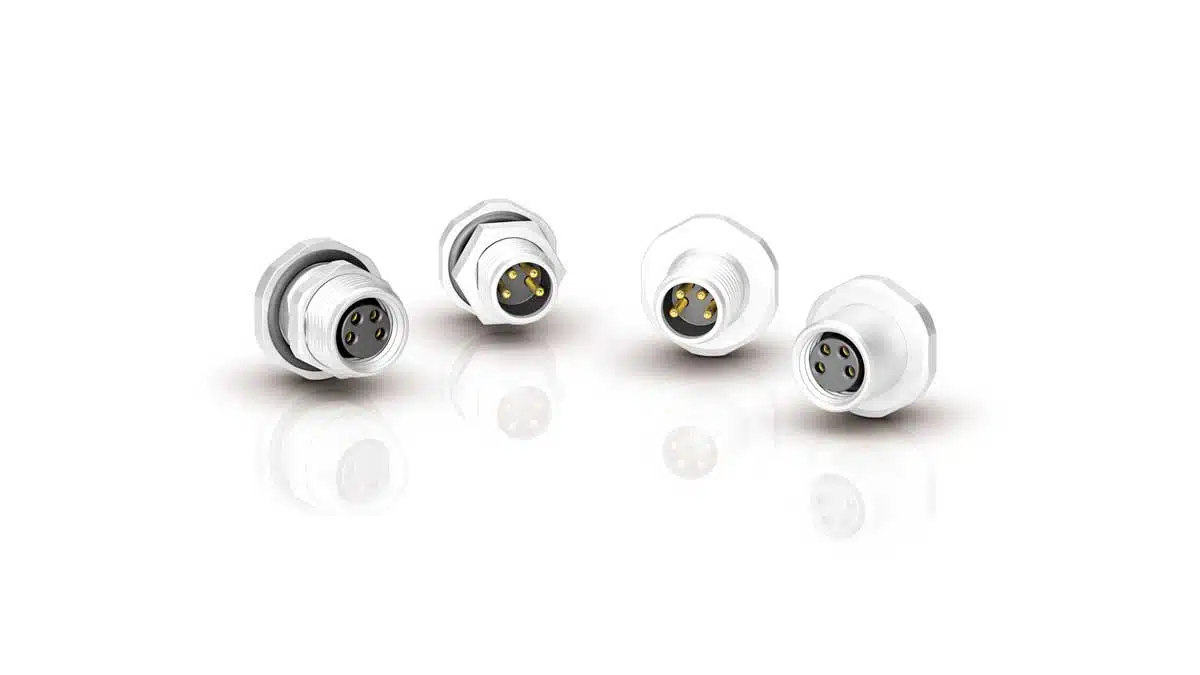
Binder has expanded its M8 circular connector portfolio with new flange connectors that use solder bucket terminations instead of pre‑molded cables or crimp contacts.

These compact, panel‑mount parts target applications where engineers need custom cable lengths, manual assembly, or small production runs while still meeting industrial protection and interface requirements. For designers and purchasing teams, they close the gap between fully customized wiring and standard cordsets in tight installation spaces.

RelatedPosts

Binder Hybrid Connector Simplifies One Cable Automation

binder Releases Tool‑Tightenable M12 Connectors for Improved Reliability

Binder Introduces Triangular Moulding for M16 and M12 Cable Connectors

Key features and benefits

The new M8 flange connectors extend the existing Binder M8 range with a version specifically optimized for manual wiring and flexible cabling strategies. Instead of being constrained to predefined leads, users can bring their own cable and terminate it directly at the connector.

Key characteristics include:

  • Flange connector design with solder bucket terminations for direct cable soldering.
  • Compliance with IEC 61076‑2‑104, ensuring mechanical and interface compatibility with standard M8 sensor and actuator systems.
  • Protection classes IP65, IP67 and IP69K when properly mounted and sealed, supporting washdown and harsh industrial environments.
  • Compact, industry‑grade construction suitable for space‑constrained machine and robotics applications.
  • Full compatibility with common M8 sensor and actuator interfaces, simplifying integration into existing architectures.
  • Availability in both flange plug (male) and flange socket (female) versions, with multiple contact counts.

For engineering teams already using M8 connectivity, the main benefit is the ability to stay within the established interface standard while tailoring harness lengths, cable types, and routing to the real mechanical constraints of the machine.

Typical applications

The solder‑connection M8 flange connectors are aimed at environments where installation space is tight and cable routing is highly application specific.

Typical use cases include:

  • Automation and conveyor technology, where sensors and actuators must be wired into compact control panels or machine frames.
  • Sensor/actuator cabling on distributed I/O modules and field junction boxes that require flexible cable entry and direction.
  • Measurement and test systems, including fixtures, jigs, and custom test setups that frequently use short or unusual cable lengths.
  • Robotic systems with limited installation space in joints, wrists, or end‑of‑arm tooling where connector depth and cable exit geometry must be controlled.
  • Retrofit and repair scenarios where existing assemblies need to be re‑cabled or adapted without replacing whole cordsets.

Because the parts are designed for manual wiring, they are well suited to low‑to‑medium production volumes, prototyping, and project‑specific machine builds where fully customized overmolded cables would not be economical.

Technical highlights

From a specification standpoint, the new M8 flange devices are standard interface parts with an emphasis on environmental robustness and flexible mounting.

Key technical points:

  • Standard M8 interface according to IEC 61076‑2‑104 for signal‑level sensor/actuator connections.
  • Protection classes IP65, IP67 and IP69K when used with appropriate sealing and mounting hardware, supporting outdoor use, washdown cleaning, and high‑pressure environments.
  • Compact flange design that keeps the connector footprint small on panels and housings.
  • Solder bucket terminations sized for direct soldering of individual conductors, enabling the use of customer‑specified cable types (for example, PUR or PVC jacket, shielded or unshielded).
  • Designed and laboratory‑tested for industrial mechanical loads and environmental conditions, focusing on long‑term reliability.

In practice, IEC 61076‑2‑104 compliance means that the mating face dimensions, contact arrangement, and locking system are controlled, so an M8 sensor or cable from a compliant ecosystem will mate reliably with these flange connectors. The IP69K rating indicates that, with correct panel sealing, the connector can withstand high‑pressure, high‑temperature spray cleaning, which is important in food, beverage, and similar demanding environments.

Design‑in notes for engineers

When designing in the new M8 flange connectors, a few practical aspects help ensure reliable installations:

  • Front vs rear mounting: Front‑mount versions are inserted from the outside of the enclosure and fixed from the inside, while rear‑mount parts are inserted from the inside and secured from the outside. The choice affects assembly sequence, sealing strategy, and serviceability.
  • Panel cut‑outs and sealing: The M10×0.75 thread is used to secure the connector in the panel. Correct hole dimensions, flatness, and suitable seals or O‑rings are important to achieve the specified IP protection classes.
  • Cable selection and strain relief: Because the termination is via solder cups, you can freely choose cable type and conductor size within the connector’s specified range. For industrial use, combine this with appropriate internal strain relief or potting so that mechanical loads are not transferred to the solder joints.
  • Contact count and pin assignment: The available 3‑ and 4‑pole variants fit typical sensor and actuator pinouts (for example, 3‑wire or 4‑wire sensors). Maintain consistent pin numbering and color coding with your existing M8 ecosystem to avoid wiring errors.
  • Assembly process: These connectors are intended for manual soldering, which is advantageous for small batches and repairs. Define work instructions for stripping length, soldering temperature, and inspection to keep contact resistance low and ensure repeatable quality.

For purchasing teams, the fact that both male and female, front and rear mount versions share the same interface simplifies stocking and second‑sourcing inside the M8 connector family. The solder‑bucket design also reduces dependence on specific overmolded cable assemblies, which can mitigate lead‑time and minimum‑order‑quantity constraints in project business.

Source

The information in this article is based on the official Binder press release on the M8 flange connectors with solder connection and the associated product detail listings. For full electrical and mechanical specifications, users should always consult the latest manufacturer datasheets.

References

  1. Binder press release: M8 flange connectors with solder connection
  2. Binder M8 automation technology product overview

Related

Recent Posts

Panasonic Releases Relays for IEC 62955 Compliant Single‑Phase EV Wallboxes

25.6.2026
6

Bourns Introduced High-Current Coupled Inductor for 48 V Hybrid and IBC Converters

24.6.2026
13

Würth Elektronik Expands Nanocrystalline Cable Cores for Broadband EMI Suppression

23.6.2026
16

EMC‑Compliant PCB and Connector Design Guidelines

22.6.2026
34

Bourns Releases Automotive Gate Driver Transformer for Isolated Power

22.6.2026
20

Knowles Expands High‑Q Ceramic Core Inductors for RF designs

19.6.2026
26

Vishay Unveils 1.5 kV IHDV High Voltage Power Inductors for EV and Industrial Converters

19.6.2026
34

SCHURTER Introduces PPTC Resettable Overcurrent Protection for Compact Electronics

18.6.2026
34

Hirose Releases Ultra‑low Profile FPC‑to‑board Connector

17.6.2026
13

Upcoming Events

Jun 30
17:00 - 18:00 CEST

PSMA Capacitor Committee Webinar: High Voltage Pulse Capacitors

Jul 14
16:00 - 17:00 CEST

EMC Design Essentials: Mastering Varistors and Common Mode Chokes

Jul 21
16:00 - 17:00 CEST

Safety by design: X and Y Interference suppression capacitors for power line filters

View Calendar

Popular Posts

  • Boost Converter Design and Calculation

    0 shares
    Share 0 Tweet 0
  • Buck Converter Design and Calculation

    0 shares
    Share 0 Tweet 0
  • LLC Resonant Converter Design and Calculation

    0 shares
    Share 0 Tweet 0
  • Flyback Converter Design and Calculation

    0 shares
    Share 0 Tweet 0
  • MLCC and Ceramic Capacitors

    0 shares
    Share 0 Tweet 0
  • Earthing Systems and IEC Classification Explained

    0 shares
    Share 0 Tweet 0
  • Nvidia Vera Rubin: Why One AI Rack Needs So Many More MLCC Capacitors

    0 shares
    Share 0 Tweet 0
  • Dual Active Bridge (DAB) Topology

    0 shares
    Share 0 Tweet 0
  • SEPIC Converter Design and Calculation

    0 shares
    Share 0 Tweet 0
  • MLCC Case Sizes Standards Explained

    0 shares
    Share 0 Tweet 0

Newsletter Subscription


Passive Components Blog

© EPCI - Leading Passive Components Educational and Information Site

  • Home
  • Privacy Policy
  • EPCI Membership & Advertisement
  • About

No Result
View All Result
  • Home
  • Knowledge Blog
  • Dossiers
  • PCNS

© EPCI - Leading Passive Components Educational and Information Site

This website uses cookies. By continuing to use this website you are giving consent to cookies being used. Visit our Privacy and Cookie Policy.
Go to mobile version