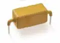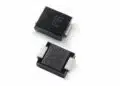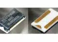


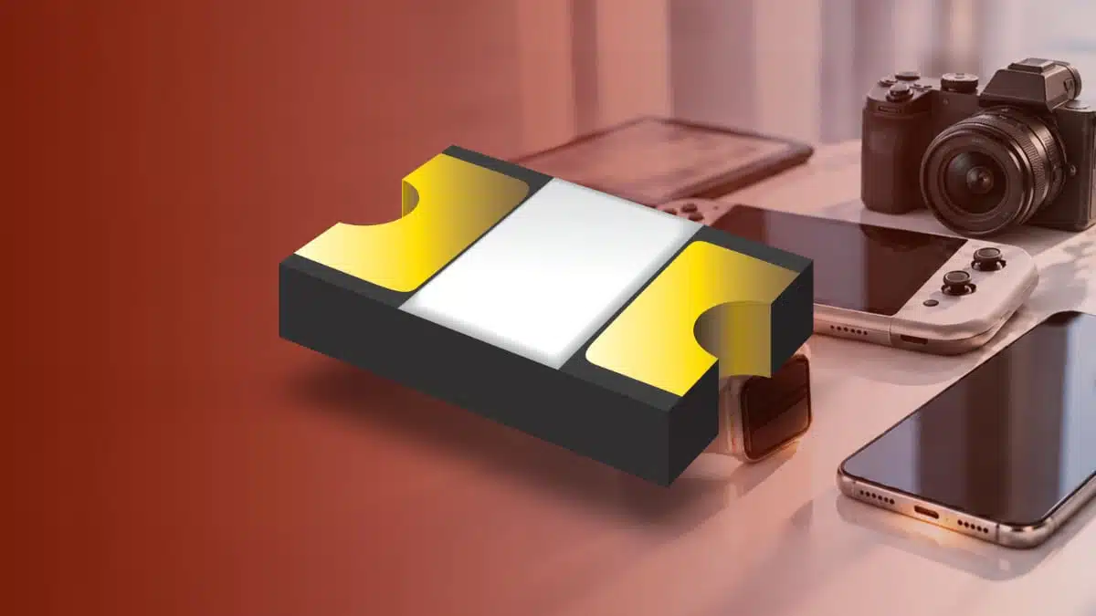
Bourns has introduced the MF-ASMF Series, a family of Multifuse polymer positive temperature coefficient (PPTC) resettable fuses in a 0402 footprint.
With hold currents from 0.05 A to 0.10 A, the series targets battery, charging, sensing and interface lines in portable electronics where board area and component height are limited.
Key features and benefits
- Three models: MF-ASMF005X, MF-ASMF008X and MF-ASMF010X
- Hold current of 0.05 A, 0.08 A or 0.10 A at 23 °C
- Maximum voltage of 9 V DC (MF-ASMF005X) or 6 V DC (MF-ASMF008X, MF-ASMF010X)
- 50 A maximum fault current for all models
- 0402 footprint, maximum 1.15 mm × 0.65 mm, maximum height 0.6 mm
- Symmetrical construction with ENIG (electroless nickel, immersion gold) terminals
- Operating temperature from −40 °C to +85 °C
- cUL recognition (file E174545) and TÜV certification (R50256634) covering IEC 62319-1, IEC 60738-1 and IEC 60730-1:2013 (clauses 15 and 17, Annex J)
- RoHS compliant and halogen free
Technical highlights
| Model | Vmax / Imax | Ihold / Itrip at 23 °C | Max. time to trip |
|---|---|---|---|
| MF-ASMF005X | 9 V DC / 50 A | 0.05 A / 0.15 A | 1.0 s at 0.25 A |
| MF-ASMF008X | 6 V DC / 50 A | 0.08 A / 0.24 A | 1.0 s at 0.40 A |
| MF-ASMF010X | 6 V DC / 50 A | 0.10 A / 0.30 A | 1.0 s at 0.50 A |
Resistance ranges from a minimum of 2.8 Ω, 2.0 Ω and 1.4 Ω to a maximum post-reflow value (R1max, measured one hour after reflow) of 25.0 Ω, 12.0 Ω and 8.0 Ω for the 005X, 008X and 010X models respectively. Typical tripped power dissipation is 0.3 W for all three.
Hold current is the highest current the device carries for 30 minutes in still air without tripping. Trip current is the level at which it reliably switches to its high-resistance state. Between the two lies a band in which behaviour depends on ambient temperature, mounting and heat flow, so a PPTC device is not a precise current limiter. Imax is the maximum fault current the device withstands at rated voltage, not a continuous rating. Further background on the operating principle is covered in the PPTC resettable fuse fundamentals and applications article.
Thermal derating
Hold current falls as ambient temperature rises, which governs sizing more than the 23 °C rating:
| Model | Ihold at −40 °C | Ihold at 60 °C | Ihold at 85 °C |
|---|---|---|---|
| MF-ASMF005X | 0.073 A | 0.037 A | 0.028 A |
| MF-ASMF008X | 0.117 A | 0.059 A | 0.045 A |
| MF-ASMF010X | 0.146 A | 0.074 A | 0.056 A |
At +85 °C, each model retains about 56 % of its 23 °C hold current. A device in a warm handheld enclosure must therefore be sized from the derated value, not from the headline rating.
Environmental and mechanical data
Passive ageing at +85 °C for 1000 hours and humidity ageing at +85 °C/85 % RH for 1000 hours each produce a typical resistance change of ±5 %. Twenty thermal-shock cycles between −40 °C and +85 °C give a typical change of ±10 %. Vibration testing follows MIL-STD-883C, Method 2007.1, Condition A. ESD classification is Class 6 per AEC-Q200-2 (HBM); this is an ESD test classification, not AEC-Q200 qualification of the series. Trip cycle life is tested with 100 cycles at Vmax and Imax, and trip endurance with 48 hours at Vmax, both without arcing or burning.
| Item | Value |
|---|---|
| Length / width / height | 0.85–1.15 / 0.35–0.65 / 0.20–0.60 mm |
| Pb-free reflow peak | 260 °C, 20–40 s within 5 °C |
| Time above 217 °C | 60–150 s |
| Packaging | 10,000 (-2) or 5,000 (-2-BV) per reel |
The parts carry no marking. Tape and reel packaging follows EIA-481. Reflow soldering is the intended process. Wave soldering is permitted only when the device sits on the top side of the board, opposite the heat source, and hand soldering is not recommended.
Typical applications
- Overcurrent protection for small Li-ion and polymer battery circuits in wearables
- Low-power battery and charging circuits in mobile devices
- I/O and signal-line protection on PC motherboards
- Sensing circuit protection
- Interface protection in handheld and portable gaming devices
- E-readers, digital cameras and other portable electronics
Application fit
The 6 V DC and 9 V DC ratings match single-cell Li-ion and low-voltage logic or interface rails. Higher-voltage buses and multi-cell packs are outside the series’ range. The 0.05 A to 0.10 A hold currents suit sensor supplies, signal lines and low-power charging paths, while the 0.6 mm maximum height and 0402 footprint allow placement in thin wearable and handheld assemblies.
Series resistance is the main trade-off at these current levels. At R1max, the voltage drop at full hold current is 1.25 V for MF-ASMF005X (0.05 A × 25 Ω) and 0.8 V for MF-ASMF010X (0.10 A × 8 Ω). On a 3.3 V sensor rail or a battery-measurement path this can be significant, and the drop belongs in the supply and error budget. Where that loss is too high, the next-higher hold-current model with lower resistance may be preferable, provided its trip current still protects the downstream circuit.
The 85 °C upper operating limit and 1.0 s maximum trip times fit consumer and portable equipment. The TÜV certification against IEC 60730-1 and IEC 60738-1 is relevant where the fuse forms part of a recognised protection function in an end product.
Design-in notes for engineers
- Size hold current from the derating table at the highest expected ambient temperature, including self-heating from nearby components, not from the 23 °C value.
- Check that the minimum credible fault current exceeds trip current at the lowest operating temperature, where the derating table gives the highest hold current. This applies especially when an upstream regulator or the battery protection IC limits current.
- Use R1max for worst-case voltage-drop and power-loss calculations.
- Keep circuit voltage, including transients, within Vmax. Inductive loads and cable inductance can generate voltages above the rated value during interruption.
- PPTC devices protect against temporary faults. They are not intended for circuits where overcurrent is repetitive or prolonged.
- Reset requires removal of the fault and power. Check that the system tolerates the tripped state at 0.3 W typical dissipation and recovers as intended.
- Allow clearance for the thermal expansion that occurs during tripping. Rigid potting, housings or coatings that constrain the device can impair operation.
- Avoid exposure to solvents, oils, gels and electrolytes. Conformal coatings and potting compounds containing solvents such as xylene or toluene must be fully cured before they contact the device.
- Follow the recommended pad layout, the reflow profile and the storage limit of +40 °C/70 % RH.
- Final selection should be validated by fault testing on the assembled board under worst-case operating conditions.
Further reading
Source
This article is based on the Bourns product announcement and official product documentation. Engineers should refer to the current manufacturer datasheet for final design and qualification.
References
- New Bourns® Multifuse® PPTC Resettable Fuses Provide Overcurrent Protection in a 0402 Footprint, Bourns, October 7, 2026
- MF-ASMF Series Multifuse® PPTC Resettable Fuses datasheet, Bourns, Rev. A, 08/26