












Passive Components Blog
No Result
View All Result
  • Home
  • NewsFilter
    • All
    • Aerospace & Defence
    • Antenna
    • Applications
    • Automotive
    • Capacitors
    • Circuit Protection Devices
    • electro-mechanical news
    • Filters
    • Fuses
    • Inductors
    • Industrial
    • Integrated Passives
    • inter-connect news
    • Market & Supply Chain
    • Market Insights
    • Medical
    • Modelling and Simulation
    • New Materials & Supply
    • New Technologies
    • Non-linear Passives
    • Oscillators
    • Passive Sensors News
    • Resistors
    • RF & Microwave
    • Telecommunication
    • Weekly Digest

    Wk 28 Electronics Supply Chain Digest

    Bourns Introduces Automotive BMS Signal Transformer with Integrated Common Mode Chokes

    Itelcond Introduces High‑Voltage Aluminium Capacitors for Modern IGBT DC‑links

    Bourns Introduces Automotive Shielded Power Inductors for Compact DC‑DC Converters

    EMC Design Fundamentals: Safe Use of Varistors and Common Mode Chokes in Mains and Data-Line Filters

    Murata Unveils Lead Disc Ceramic Capacitors for Automotive Safety and EMI Suppression

    SCHURTER Releases Intelligent Three‑Terminal Fuses for Safer Li‑ion Battery Systems

    Can Copper Conductive Inks Displace Silver in Hybrid Electronics?

    Square-Wave Harmonics and RMS Currents in Power Converters

    Trending Tags

    • Ripple Current
    • RF
    • Leakage Current
    • Tantalum vs Ceramic
    • Snubber
    • Low ESR
    • Feedthrough
    • Derating
    • Dielectric Constant
    • New Products
    • Market Reports
  • VideoFilter
    • All
    • Antenna videos
    • Capacitor videos
    • Circuit Protection Video
    • Filter videos
    • Fuse videos
    • Inductor videos
    • Inter-Connect Video
    • Non-linear passives videos
    • Oscillator videos
    • Passive sensors videos
    • Resistor videos

    EMC Design Fundamentals: Safe Use of Varistors and Common Mode Chokes in Mains and Data-Line Filters

    Ferrite versus Nanocrystalline Power Inductor Cores: Turns, Gap and Size

    KYOCERA AVX Presents Antenna Integrator Studio Tutorial for Antenna Placement and RF Design

    Power Design Simulation Tools for Faster Inductor Selection and Loss Optimization

    EMC‑Compliant PCB and Connector Design Guidelines

    Why Isolated DC/DC Power Supplies Fail Late, Würth Elektronik Podcast

    Designing 800 V DC EMC Filters: Calculation, Simulation and Measurement

    Current Sense Transformer Datasheet and Design‑in Guide

    Designing a USB Type‑C Flyback Planar Transformer with Frenetic’s Planar Tool

    Trending Tags

    • Capacitors explained
    • Inductors explained
    • Resistors explained
    • Filters explained
    • Application Video Guidelines
    • EMC
    • New Products
    • Ripple Current
    • Simulation
    • Tantalum vs Ceramic
  • Knowledge Blog
  • Dossiers
    • AI Hardware Dossier
    • Power Converter Dossier
    • Automotive Dossier
    • Capacitor Dossier
    • Resistor Dossier
    • Inductor Dossier
    • Circuit Protection Dossier
  • Suppliers
    • Who is Who
  • PCNS
    • PCNS 2025
    • PCNS 2023
    • PCNS 2021
    • PCNS 2019
    • PCNS 2017
  • Events
  • Home
  • NewsFilter
    • All
    • Aerospace & Defence
    • Antenna
    • Applications
    • Automotive
    • Capacitors
    • Circuit Protection Devices
    • electro-mechanical news
    • Filters
    • Fuses
    • Inductors
    • Industrial
    • Integrated Passives
    • inter-connect news
    • Market & Supply Chain
    • Market Insights
    • Medical
    • Modelling and Simulation
    • New Materials & Supply
    • New Technologies
    • Non-linear Passives
    • Oscillators
    • Passive Sensors News
    • Resistors
    • RF & Microwave
    • Telecommunication
    • Weekly Digest

    Wk 28 Electronics Supply Chain Digest

    Bourns Introduces Automotive BMS Signal Transformer with Integrated Common Mode Chokes

    Itelcond Introduces High‑Voltage Aluminium Capacitors for Modern IGBT DC‑links

    Bourns Introduces Automotive Shielded Power Inductors for Compact DC‑DC Converters

    EMC Design Fundamentals: Safe Use of Varistors and Common Mode Chokes in Mains and Data-Line Filters

    Murata Unveils Lead Disc Ceramic Capacitors for Automotive Safety and EMI Suppression

    SCHURTER Releases Intelligent Three‑Terminal Fuses for Safer Li‑ion Battery Systems

    Can Copper Conductive Inks Displace Silver in Hybrid Electronics?

    Square-Wave Harmonics and RMS Currents in Power Converters

    Trending Tags

    • Ripple Current
    • RF
    • Leakage Current
    • Tantalum vs Ceramic
    • Snubber
    • Low ESR
    • Feedthrough
    • Derating
    • Dielectric Constant
    • New Products
    • Market Reports
  • VideoFilter
    • All
    • Antenna videos
    • Capacitor videos
    • Circuit Protection Video
    • Filter videos
    • Fuse videos
    • Inductor videos
    • Inter-Connect Video
    • Non-linear passives videos
    • Oscillator videos
    • Passive sensors videos
    • Resistor videos

    EMC Design Fundamentals: Safe Use of Varistors and Common Mode Chokes in Mains and Data-Line Filters

    Ferrite versus Nanocrystalline Power Inductor Cores: Turns, Gap and Size

    KYOCERA AVX Presents Antenna Integrator Studio Tutorial for Antenna Placement and RF Design

    Power Design Simulation Tools for Faster Inductor Selection and Loss Optimization

    EMC‑Compliant PCB and Connector Design Guidelines

    Why Isolated DC/DC Power Supplies Fail Late, Würth Elektronik Podcast

    Designing 800 V DC EMC Filters: Calculation, Simulation and Measurement

    Current Sense Transformer Datasheet and Design‑in Guide

    Designing a USB Type‑C Flyback Planar Transformer with Frenetic’s Planar Tool

    Trending Tags

    • Capacitors explained
    • Inductors explained
    • Resistors explained
    • Filters explained
    • Application Video Guidelines
    • EMC
    • New Products
    • Ripple Current
    • Simulation
    • Tantalum vs Ceramic
  • Knowledge Blog
  • Dossiers
    • AI Hardware Dossier
    • Power Converter Dossier
    • Automotive Dossier
    • Capacitor Dossier
    • Resistor Dossier
    • Inductor Dossier
    • Circuit Protection Dossier
  • Suppliers
    • Who is Who
  • PCNS
    • PCNS 2025
    • PCNS 2023
    • PCNS 2021
    • PCNS 2019
    • PCNS 2017
  • Events
No Result
View All Result
Passive Components Blog
No Result
View All Result

Achieve Longer Lifespans with 3.0V EDLC Supercapacitors

5.2.2025
Reading Time: 7 mins read
A A
Full paper download

Electrical Double Layer Capacitors (EDLC) supercapacitors have shown significant growth in the last several years.

This paper by Vishay presents 3.0V EDLC supercapacitors and its benefits to achieve a longer useful life and also meet the stronger and more harsh requirements with regard to high humidity and low losses over a wide temperature range.

RelatedPosts

Vishay Unveils Multi-Turn Position Sensor for Harsh Industrial Environments

Vishay Introduces SMD Polymer PTC Thermistors for Fast Resettable Overcurrent Protection

Vishay Unveils 1.5 kV IHDV High Voltage Power Inductors for EV and Industrial Converters

This paper was presented by Gerald Tatschl, Vishay BCcomponents Austria at the 4th PCNS 10-14th September 2023, Sønderborg, Denmark as paper No.1.3.

Introduction

A select number of manufacturers have expanded their offerings to include 3.0 V EDLC products, augmenting their existing 2.7 V lines. These newly developed products are designed to have a more extensive lifespan, incorporating innovative features that can withstand harsh conditions like high humidity, while maintaining minimal losses across a broad temperature range.

Electrical Double Layer Capacitors (EDLC) have been experiencing remarkable growth over the past few years. These devices serve as high-capacity rechargeable energy storage systems, distinguished by their ability for swift charge and discharge cycles. Owing to their exceptionally low internal resistance (ESR), EDLCs are capable of delivering and absorbing high peak power, making them perfectly suited for booster applications. They also maintain consistent capacity and storage capabilities across varying temperatures.

One of the standout features of EDLC products is their potential to undergo limitless charge and discharge cycles, extending the operational lifespan of battery systems. In some instances, they can reduce or even eliminate the need for a battery in certain applications, making them a valuable asset in backup, energy harvesting, and self-powered IoT applications.
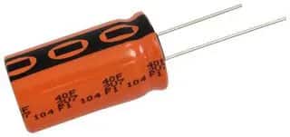
EDLCs have a competitive edge over batteries, as they can be charged considerably quicker. The introduction of 3 V EDLC products has further enhanced this advantage as they can store 20 % more energy than a comparable 2.7 V system of the same dimensions.

Furthermore, the larger voltage window of these 3 V components can prolong device life, save space, and reduce costs on the PCB.

The current line of 3 V Vishay products has been designed to directly replace the older 2.7 V versions, promising a two to three times longer service life.

General EDLC Supercapacitor Technology Overview

Vishay’s Electrical Double Layer Capacitors (EDLC) are quintessential supercapacitors featuring a radial design. Even in this configuration, an EDLC is capable of achieving extremely high capacitance values, reaching up to 100 F. This technology bridges the gap between traditional aluminum electrolytic capacitors and rechargeable batteries.

Supercapacitors can store considerably more energy than conventional aluminum capacitors. Another key advantage is their ability to produce high discharge currents, which sets them apart from rechargeable batteries. Furthermore, EDLCs can withstand an impressive number of charge and discharge cycles, exceeding one million in count.

EDLCs have found applications in various areas such as backup power supplies, burst power support, and energy harvesting storage devices. They are also utilized in micro-UPS systems and energy recovery mechanisms.

Specific Characteristics

Fig. 1 Electrostatic Helmholtz EDLC I = 0

The basic structure of an EDLC consists of two activated carbon electrodes separated by a paper and an electrolyte that electrically connects the two electrodes (Fig. 1).

EDLC capacitors use the so-called double layer effect to store electrical energy. A double layer capacitor has no solid dielectric separating the different potentials. The electrodes are polarized by an applied voltage.

This causes the ions in the electrolyte to form electrical double layers on the two electrode surfaces. This physical effect enables the high energy density of this capacitor technology.

As a result of self-discharge, the charge retention of EDLC products is limited to a few weeks.

The useful lifetime of an EDLC is temperature- and voltage-dependent. A 10 °K lower temperature will double the lifetime, and a 200 mV lower applied voltage will double the lifetime as well. This principle is derived from the well- known Arrhenius law on the acceleration of reaction processes. To ensure full performance even in elevated humidity conditions, Vishay has developed rugged EDLC versions such as the 225 EDLC-R and 235 EDLC-HVR.

If more than two capacitors are in a series connection, it is necessary to balance the products. Otherwise, a voltage mismatch may occur.

The advantage of “ruggedized” EDLC variants is that these products can withstand harsher environmental conditions than standard versions.

Tests have shown that these “ruggedized” variants achieve service lives of 1500 hours and even longer at 85 °C / 85 % RH (source: Vishay, 235 EDLC-HVR datasheet). According to the IEC standard, only 1000 hours are required for these components.[1]

Calculation

In general, the lifetime of EDLCs is limited by degradation of electrical parameters. Usually, no sudden failures occur. The lifetime of EDLC systems is mainly dependent on the application’s ambient temperature and applied voltage.

An Arrhenius approximation is sufficient to describe lifetime t within limits. Commonly used acceleration factors / activation energies for EDLC models are:

Temperature T:                  activation energy ∆T = 10K

Voltage U:                          activation energy ∆U = 0.2V

rule: Temperature reduction of ∆T = 10K (°C) doubles the lifetime

rule: Voltage reduction of ∆U = 0.2 V doubles the lifetime
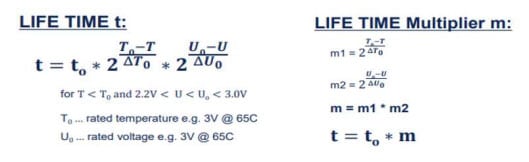
Fig. 2. Lifetime calculation [2]

3V EDLC Supercapacitors Life-time Benefits

Supercapacitor service life can be determined using the multiplier diagram (Fig. 3), which shows the service life expectancy as a function of the ambient temperature and the applied voltage.

Fig. 3. Multiplier graph for 3V EDLC products

The specified rated voltage UR can be applied in the temperature range -40 °C to +65 °C. From +65 °C to +85 °C, a linear voltage derating needs to be applied.

The following diagram, Fig. 4, shows the safe operating range for the working voltage of 2.7 V and 3.0 V systems.

Fig. 4. Voltage and temperature derating of 3V and 2.7V supercapacitors

Arrhenius modeling is standard for lifetime (t) prediction. The acceleration factors and the simplified formula for multiplier calculation are commonly used in the industry.

The typical degradation behavior of the supercapacitor resembles that of an exponential decay. The better part of the performance change occurs during the initial use of the capacitor, then levels off over time. The most dramatic effect of the life degradation is on the internal resistance of the device (compared to initial value). This effect is taken into account in the product specifications, therefor the specified maximum initial ESR is higher than the typical value.

Summary & Conclusion

This article looks into the enhanced longevity offered by 3 V products compared to the standard 2.7 V counterparts. The optimization of service life is a key advantage of 3 V EDLC systems. It demonstrates that supercapacitors can potentially exceed a 10-year lifespan, even at temperatures above room level. Future trends indicate a focus on developing products that can withstand higher application temperatures and come in more compact case sizes.

References

  • Vishay BCcomponents Austria, dokuwiki

  • Supercapacitors, G.Q. Max Lu et. al; Wiley-CHV; ISBN 978-3-527-32883-3; 2013;p483ff
  • Vishay BCcomponents Austria, dokuwiki

Source: EPCI

Recent Posts

Itelcond Introduces High‑Voltage Aluminium Capacitors for Modern IGBT DC‑links

17.7.2026
51

EMC Design Fundamentals: Safe Use of Varistors and Common Mode Chokes in Mains and Data-Line Filters

16.7.2026
86

Murata Unveils Lead Disc Ceramic Capacitors for Automotive Safety and EMI Suppression

15.7.2026
59

Square-Wave Harmonics and RMS Currents in Power Converters

14.7.2026
64

LeanBOM: Practical Cross‑Technology Capacitor Search by Real Working Conditions

14.7.2026
64

In the Age of AI, Every Watt Counts: Implications for Components

13.7.2026
99

RF Filters and Passive Components Enabling the 7 Missile RF Subsystems

9.7.2026
65

Ferrite versus Nanocrystalline Power Inductor Cores: Turns, Gap and Size

9.7.2026
90

From DCL to SSC: Bridging Electrical Symptoms and Structural Indicators in Tantalum Capacitors

7.7.2026
68

Upcoming Events

Jul 28
8:00 - 11:00 CEST

Post Procurement Testing of EEE Components for LEO Space Applications

Jul 29
17:30 - 18:30 CEST

To Ferrite or to Nanocrystalline in Transformer Design

Sep 29
16:00 - 17:00 CEST

Cybersecurity 2026

View Calendar

Popular Posts

  • Boost Converter Design and Calculation

    0 shares
    Share 0 Tweet 0
  • Buck Converter Design and Calculation

    0 shares
    Share 0 Tweet 0
  • YAGEO Announces July 2026 Capacitor Price Increase

    0 shares
    Share 0 Tweet 0
  • Flyback Converter Design and Calculation

    0 shares
    Share 0 Tweet 0
  • LLC Resonant Converter Design and Calculation

    0 shares
    Share 0 Tweet 0
  • MLCC and Ceramic Capacitors

    0 shares
    Share 0 Tweet 0
  • MLCCs in the Age of AI: Q2 2026 Market Tightness

    0 shares
    Share 0 Tweet 0
  • Earthing Systems and IEC Classification Explained

    0 shares
    Share 0 Tweet 0
  • Nvidia Vera Rubin: Why One AI Rack Needs So Many More MLCC Capacitors

    0 shares
    Share 0 Tweet 0
  • Dual Active Bridge (DAB) Topology

    0 shares
    Share 0 Tweet 0

Newsletter Subscription


Passive Components Blog

© EPCI - Leading Passive Components Educational and Information Site

  • Home
  • Privacy Policy
  • EPCI Membership & Advertisement
  • About

No Result
View All Result
  • Home
  • Knowledge Blog
  • Dossiers
  • PCNS

© EPCI - Leading Passive Components Educational and Information Site

This website uses cookies. By continuing to use this website you are giving consent to cookies being used. Visit our Privacy and Cookie Policy.










