















This article, written by Vladimir Azbel, Ph.D., a semiconductor process reliability engineering consultant, and adapted and edited for passive-components.eu, reviews mechanical SSC testing of tantalum capacitor anodes as a means of assessing tantalum capacitor reliability and performance.
The focus of this article is how SSC testing can be used not only as a mechanical measurement, but as a structural diagnostic framework tool for benchmark comparison, process diagnostics, post-stress analysis, and reliability interpretation. Simply: from electrical pass/fail to benchmark-based root-cause and reliability analysis of tantalum capacitors.
The article follows and conclude the previous posts published on passive-components.eu:
- Powder Stress–Strain Curves for Tantalum Capacitors Reliability – SSC diagnostics at powder/pellet level, direct “previous step” to this article.
- Benefits of Tantalum Powder Stress–Strain Curve Evaluation vs Conventional Wet Test – Introduces SSC vs wet testing and mechanical criteria for powder quality.
- Energy Localization in Tantalum Anode Formation – A Structural Perspective – Directly supports the thermal/localization part of your SSC + thermal model discussion.
- How a Digital Structural Twin Can Predict Tantalum Capacitor Reliability – Shows the next step: using SSC-based structural diagnostics within a digital twin framework.
- Using Stress–Strain Curves to Diagnose Tantalum Powders for Capacitors – Explains SSC curve and its parameters in more details
Introduction
In standard production practice, quality control is mainly based on electrical testing of the finished component. This is necessary, but it usually tells only whether a capacitor passed or failed. It does not always explain why the observed behavior occurred or what structural condition of the anode produced the result.
This article presents mechanical stress–strain curve (SSC) testing as a structural diagnostic framework for tantalum capacitor anodes. The purpose of the method is not to replace electrical testing, but to complement it with a physically interpretable structural layer that supports root-cause analysis, benchmarking, and reliability assessment.
Why go beyond electrical pass/fail?
Modern quality control for tantalum capacitors is dominated by electrical testing of the finished component. Electrical parameters confirm whether the part meets specification, whether DC leakage current (DCL) remains within limits, and whether the product passes qualification or life testing.
However, electrical testing mainly records the outcome: the component either passed or failed. It verifies performance, but it does not necessarily reveal the structural origin of that behavior. For process engineers, product developers, and reliability specialists, an equally important question is not only “did it pass or fail?” but “what anode structure produced this result?”
To answer this, mechanical SSC testing is proposed as a structural diagnostic framework for porous tantalum anodes. The methodology is based on the premise that capacitor reliability is determined not only by final electrical parameters, but also by the structural state of the anode: interparticle neck geometry, porosity, contact conditions, residual stresses, defectiveness, and stability of the sintered structure.
Core elements of the framework
The proposed approach is built on four main elements:
- SSC analysis of the mechanical signature of the porous structure through the parameters Ay, K2, and E.
- Benchmark comparison with anodes or pellets whose structure has already been associated with acceptable electrical and reliability behavior.
- Interpretation of SSC curve changes as indicators of technological drift, structural defectiveness, or changes in internal stress state.
- A thermal model linking structural changes with local neck resistance, heat generation, thermal balance, and DCL degradation risk.
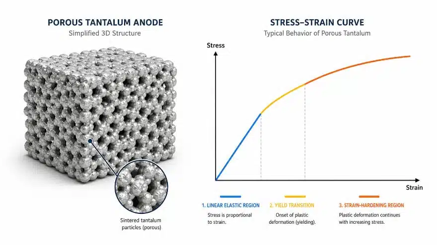
Within this framework, mechanical SSC testing becomes more than a mechanical measurement. It becomes a tool for moving from traditional pass/fail acceptance to benchmark-based structural diagnostics and reliability interpretation across the full capacitor lifecycle.
A key novelty of this approach is that mechanical SSC testing provides two complementary levels of prediction. The first is initial structural risk: whether the powder, pressing, and sintering process have formed a porous anode structure close to a qualified benchmark. The second is aging stability risk: whether this already formed structure remains mechanically and structurally stable after thermal, electrical, or reliability-related stress.
In addition to early structural diagnostics, SSC testing can therefore be used as an accelerated structural stability assessment tool. By comparing the mechanical signature of a formed or extracted anode before and after thermal aging, the method can quantify structural drift of the porous framework. A higher Mechanical Drift Index indicates increased risk of DCL instability and reliability-test failures.
It can be applied in three main ways:
- During manufacturing, to detect structural drift before it affects final yield.
- During comparative benchmarking, to evaluate realized porous structures from different manufacturers.
- After reliability testing, to interpret structural evolution and DCL degradation risk.
From pass/fail to structural root cause
Conventional electrical control follows a simple logic: component passed or component failed. Structural diagnostics allows a deeper question to be asked: what in the anode structure led to this behavior or increased the risk of degradation?
In this interpretation, the SSC curve parameters Ay, K2, and E are not only mechanical characteristics, but also structural indicators of the porous anode state:
- Ay reflects the effectiveness of the load-bearing network of interparticle contacts and necks.
- E relates to the overall stiffness of the porous structure and its density–porosity state.
- K2 is sensitive to strain localization, defectiveness, and changes in the mechanism of plastic deformation.
Mechanical testing therefore makes it possible to observe not only the final electrical result, but also the structural state that produced it.
Diagnostics of the manufacturing process
The first application of SSC testing is structural control during the anode manufacturing process, including powder preparation, pressing, sintering, deoxidation, lead-to-pellet welding, and formation. Earlier work by the author focused mainly on powder and the sintered pellet, and on how pellet structure influences future anode defectiveness.
Here, SSC testing is especially valuable because it allows the current structure to be compared not with an abstract norm, but with a benchmark structure that has already demonstrated acceptable behavior in the finished product. This means a manufacturer can control not only the final electrical result, but also structural conformity at earlier production stages.
If a batch is formally produced according to the same recipe, but the SSC parameters deviate from the benchmark, this may indicate technological drift such as:
- Changes in powder morphology.
- Changes in pressing conditions.
- Changes in sintering regime.
- Changes in interparticle neck condition.
- Changes in residual stress state.
In this case, mechanical testing becomes not just a rejection tool, but an instrument for identifying the physical cause of deviation before it develops into large-scale electrical yield loss.
Comparing anodes from different manufacturers
The second application is comparative analysis of tantalum capacitor anodes of the same or similar design, but produced by different manufacturers. This is particularly important from an industrial and competitive perspective.
Different manufacturers may offer parts with similar nominal parameters such as capacitance, voltage rating, DCL limits, and case size. However, similar electrical specifications do not guarantee the same realized porous structure inside the capacitor.
The methodology makes it possible to use commercially available finished capacitors in a structured way:
- Measure the electrical parameters.
- Perform stripping.
- Extract the anode.
- Determine anode dimensions, mass, and sintering density.
- Estimate formation voltage from oxide color.
- Perform SSC testing on the extracted anode.
Stripping itself is not a new procedure; it belongs to the classical failure-analysis toolbox. What is new here is its diagnostic meaning. The extracted anode is treated not only as a post-mortem object, but as a carrier of the realized structural signature of the finished product.
After stripping, the anode can be subjected to SSC testing, compared with the benchmark structure, and analyzed through Ay, K2, E, and the morphology of the stress–strain curve. In combination with the thermal model, this shifts the analysis from the classical FA question “what failed?” to the deeper structural question “what anode structure was formed, how does it differ from the benchmark, and how may these differences affect DCL, local overheating, and the risk of further degradation?”
This approach reveals what structure is actually being sold on the market under similar electrical specifications. It does not attempt to expose proprietary manufacturing processes; rather, it offers a benchmark-based comparison of realized product structures.
For manufacturers, this can be useful for:
- Understanding how competitive their structure is.
- Identifying strengths such as high density or stable neck geometry.
- Identifying possible improvement areas such as defectiveness, neck stability, or sensitivity to degradation.
In this sense, mechanical SSC testing becomes a technical benchmarking tool both within one’s own production and relative to the market.
Monitoring structural evolution after testing
The third application of SSC testing is the analysis of what happens to the structural state of the anode after reliability testing under different conditions.
For example, after life testing, reverse-bias stress, high-temperature storage, or other reliability tests, anodes can be extracted and their SSC curves compared with the initial benchmark structure. If DCL degradation is observed after testing, the key question becomes: what changed in the anode and in the Ta / Ta₂O₅ / interface system, and how do these changes affect local thermal risk?
Every electrical test imposes a physical load on the anode. DC leakage current flows while temperature, electric field, and exposure time act simultaneously. Even when these conditions do not visibly alter the macrogeometry of the porous structure, they can still change the internal stress-related and physicochemical state of the anode.
According to the author’s observations, changes in Ay and K2 consistently reflected the observed changes in DCL. This suggests that DCL degradation should not be treated as an isolated electrical effect. In most cases, it reflects a change in the state of the oxide–interface–tantalum system.
Probable mechanisms include:
- Diffusion processes between tantalum and the amorphous Ta₂O₅ film through the interface zone.
- Oxygen redistribution.
- Relaxation or growth of internal stresses.
- Changes in the defect state of the oxide.
- Loss of stability of the amorphous structure.
Under the influence of test conditions, these processes may increase the risk of aging and DCL instability.
Linking SSC changes to thermal risk
Mechanical interpretation alone is not sufficient to assess DCL risk. For this reason, the framework includes a thermal model of the anode that connects structural changes with local thermal behavior in the interparticle neck region.
In this model, structural changes propagate through a chain of local effects:
- Change in structure.
- Change in effective neck geometry.
- Change in local neck resistance .
- Change in local heat generation .
- Change in thermal balance .
- Change in the risk of DCL degradation.
The key parameter is the local thermal balance:
where characterizes the ability of the structure to remove heat, and represents local heat generation in the most vulnerable parts of the porous structure.
If SSC parameters shift relative to the benchmark after testing, this may indicate not only a change in the mechanical signature, but also a change in local thermal balance conditions. For example, changes in Ay may reflect the local influence of defects, interparticle contact conditions, and internal stresses, while changes in K2 show how these local changes are expressed throughout the anode volume and influence overall deformation behavior.
In this framework, the thermal model becomes the link between mechanical testing and electrical degradation. SSC testing shows that the structure has changed, while the thermal model evaluates whether this change can increase local overheating, disturb thermal balance, and raise the risk of further DCL instability.
Therefore, post-stress analysis should include:
- Comparison of SSC curves before and after testing.
- Assessment of how the detected structural changes influence local thermal risk in the anode.
Mechanical SSC testing together with the thermal model therefore becomes a tool not only for recording DCL degradation, but also for its physical interpretation. It helps explain how changes in the internal state of the anode, caused by current, temperature, electric field, and time, may alter local thermal balance and influence further aging.
This shifts the analytical focus from the simple question “has DCL changed?” to the more important question “what structural change modified the local thermal balance of the anode and thereby increased the risk of further DCL degradation?”
Why this matters for high-reliability applications
The main value of this approach is that it expands the traditional quality-control system rather than replacing it. Electrical testing remains essential and shows the consequences, while mechanical SSC testing helps explain those electrical results at the structural level. Combined with the thermal model, it links structural changes to local thermal risk and long-term DCL stability.
This is especially important for high-reliability applications, where hidden defects in the anode may not appear immediately, but may affect long-term DCL stability and failure probability.
In practice, mechanical SSC testing can serve as:
- A tool for technological diagnostics.
- A tool for comparing anodes from different manufacturers.
- A tool for analyzing degradation after testing.
- A tool for root-cause analysis in cases of DCL instability.
- Part of a predictive reliability framework for tantalum capacitors.
Summary
For tantalum capacitors, it is not enough to know only whether a component passed or failed an electrical test. It is equally important to understand what anode structure was formed, how closely it matches a proven benchmark, how it changes after testing, and whether this structural evolution can explain future DCL degradation.
The main value of the proposed framework is that mechanical SSC testing does not replace electrical testing, but physically interprets its results. Electrical control shows how the finished capacitor behaves, while SSC analysis, benchmark comparison, and the thermal model help explain what anode structure produced this behavior and how stable it may remain during long-term operation.
This makes the approach especially relevant for high-reliability applications, where it is important not only to record the fact of failure or DCL degradation, but also to identify structural causes, assess aging risk, and predict future behavior. By adding a structural diagnostic layer to conventional electrical control, mechanical SSC testing helps transform reliability analysis from simple pass/fail evaluation into benchmark-based root-cause and long-term reliability assessment.
Further read articles by V.Azbel:
- Tantalum Capacitor Anode Manufacturing Quality Management
- Reliability of Tantalum Capacitors: the Role of Internal Stress
- Innovative Quality Control to Improve the Reliability of Tantalum Capacitors
- Enhancement of Tantalum Capacitors Reliability – Innovative Approach to Anode Production Control
- Tantalum Capacitor Anode Quality: Wet vs. Mechanical Testing
- Influence of Tantalum Capacitor Pellets Size on Stability During Oxide Film Formation
- When More Capacitance Hurts Reliability: the Role of the Metallic Skeleton in Tantalum Anodes
- Enhanced Process Control in Tantalum Capacitor Anode Manufacturing Reduces Cost and Improves Reliability