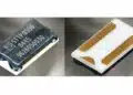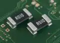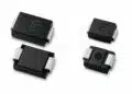


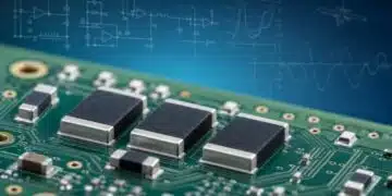


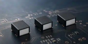




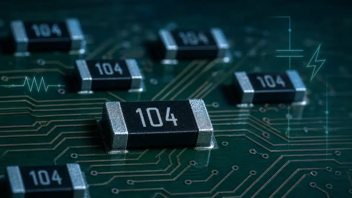
Stackpole Electronics has introduced the RVCU series of high‑voltage chip resistors, targeting precision voltage divider, sensing, and measurement circuits operating at elevated voltages.
The chip resistor series combines high working voltages with low voltage coefficient of resistance (VCR), making it attractive for designers who need accurate, stable feedback and measurement paths under changing voltage and environmental conditions.
Key features and benefits
- Low voltage coefficient of resistance (VCR): VCR specified as low as 25 ppm to 50 ppm, depending on resistance value, significantly reducing voltage‑dependent error compared with conventional high‑voltage chip resistors that can exhibit VCR values up to 300 ppm and beyond. This directly benefits precision divider and sensing designs by limiting gain error caused by changing applied voltage.
- High working voltage capability: Available in 1206, 2010, and 2512 chip sizes with maximum working voltages from 800 V up to 3000 V, enabling compact high‑voltage dividers and measurement paths without resorting to bulky through‑hole solutions or long series strings of lower‑voltage parts.
- Precision tolerance and stable TCR: Tolerance options down to 0.5% and temperature coefficient of resistance (TCR) of 100 ppm support consistent resistance values over temperature, helping maintain calibration and accuracy in precision measurement and control systems.
- Anti‑sulfur construction: Anti‑sulfur design compliant with ASTM‑B‑905‑5 mitigates resistance drift and open‑circuit failures in sulfur‑rich environments such as industrial atmospheres, automotive exhaust areas, and polluted urban installations, improving long‑term reliability.
- Safety and compliance: Compliance with IEC‑62368 for values from 75 kΩ to 27 MΩ supports use in audio/video and communications equipment that must meet modern safety standards, simplifying approvals and documentation.
- AEC compliance: The series is described as well suited for compact, high‑voltage designs requiring reliability and long‑term stability due to AEC compliance, which is particularly relevant for automotive and other demanding applications where qualification regimes are stringent.
- Global support and distribution: Stackpole positions the RVCU series within a broad resistor portfolio, backed by global manufacturing and distribution, which is important for volume projects and multi‑site production.
Typical applications
The RVCU high‑voltage chip resistors are aimed at circuits where high working voltage, accuracy, and long‑term stability are all critical.
- High‑voltage LED lighting drivers, where the resistors can provide accurate feedback or current sensing across wide line and load conditions in compact, high‑voltage front‑ends.
- Medical equipment, for example high‑voltage supplies, defibrillator charging paths, x‑ray or imaging systems that require stable high‑voltage dividers for monitoring and control.
- Audio/video and communications systems that must comply with IEC‑62368, using high‑voltage resistors for isolation monitoring, surge handling, or protection networks without sacrificing accuracy.
- Test and measurement instruments, including high‑voltage meters, probes, and power analyzers that rely on low‑VCR divider chains for precise scaling of high voltages.
- High‑voltage divider networks for transmission and control applications, such as control cabinets and high‑voltage power supplies where compact SMT dividers simplify board layout and assembly.
In practice, any design that currently uses long series strings of standard resistors to achieve both voltage rating and accuracy may benefit from consolidating into fewer RVCU parts, simplifying layout and potentially improving repeatability.
Technical highlights
The RVCU series combines specific package options and performance parameters optimized for high‑voltage divider service. Exact numerical values for all options should be taken from the manufacturer datasheet for the latest and most complete information.
Package sizes and working voltages
| Package size | Typical usage context | Maximum working voltage (according to datasheet) |
|---|---|---|
| 1206 | Space‑constrained, medium‑voltage sections | 800 V class, per manufacturer datasheet |
| 2010 | Higher creepage, higher power tracks | Up to around mid‑range kV, per datasheet |
| 2512 | Highest voltage and power in series | Up to 3000 V working voltage, per datasheet |
For design‑in, engineers should cross‑check creepage/clearance on the PCB and the layout rules of their end application standard, since the maximum working voltage assumes appropriate board design and insulation distances.
Performance parameters
- VCR (voltage coefficient of resistance):
- As low as 25 ppm to 50 ppm, depending on resistance value.
- Lower VCR means that the resistance changes only slightly as voltage increases, translating into lower gain error in high‑voltage dividers.
- TCR (temperature coefficient of resistance):
- Specified as 100 ppm, indicating that resistance changes modestly with temperature, which helps preserve calibration over normal operating ranges.
- Resistance range:
- Values between 75 kΩ and 27 MΩ are specifically mentioned in connection with IEC‑62368 compliance. The full resistance range should be confirmed from the current datasheet and line card.
- Construction and reliability:
- Anti‑sulfur construction per ASTM‑B‑905‑5, aiming to prevent sulfide growth and open circuits in polluted atmospheres.
- AEC compliance (e.g., AEC‑Q200) supports use in automotive and other harsh environments; the exact qualification level should be verified in the datasheet.
Because RVCU parts target high‑voltage dividers, their combination of high resistance values, high working voltage, and controlled VCR is intended to minimize both power dissipation and voltage‑dependent error while still fitting into standard SMT footprints.
Design‑in notes for engineers
When using the RVCU resistor series in new or existing designs, several practical points can help extract maximum benefit from the low VCR and high‑voltage capability.
- Consider total divider error budget: Combine the specified tolerance, TCR, and VCR into the overall error budget for the voltage measurement or feedback loop. In high‑voltage dividers, the VCR can dominate error at elevated voltages, so switching from conventional high‑VCR parts to RVCU can significantly reduce the total error.
- Optimize resistance values for power and noise: Higher resistance values reduce power dissipation and heat, but increase susceptibility to leakage and noise. The available range from 75 kΩ to 27 MΩ, according to manufacturer information, allows trade‑offs between power, bandwidth, and noise.
- Mind creepage and clearance on the PCB: Although the resistor body supports up to 3000 V working voltage in the largest size, actual safe operation depends on PCB layout and environmental pollution degree. Ensure board spacing and coating align with the working voltage and applicable safety standards such as IEC‑62368.
- Use anti‑sulfur benefits in harsh environments: For designs in industrial, automotive, or outdoor environments with higher sulfur exposure, the anti‑sulfur construction helps maintain long‑term stability and avoid unexpected open circuits, particularly where field access is difficult.
- Align with safety and compliance requirements: For audio/video, ICT, and similar equipment governed by IEC‑62368, using IEC‑compliant resistance ranges simplifies documentation and certification. Verify that the chosen resistance values fall within the specified compliant range.
- Check AEC qualification needs: For automotive or transportation applications, confirm the exact AEC qualification level of the RVCU series and match it with OEM requirements. This can avoid complications during design audits or PPAP processes.
- Plan for supply and lifecycle: As Stackpole is a global manufacturer with long history and multiple production sites, RVCU can serve as a long‑term platform part for multiple platforms. Coordinate with purchasing to establish preferred values and stocking strategies across projects.
Practical example: high‑voltage measurement divider
In a high‑voltage power supply or inverter, a designer may need to scale several kilovolts down to a safe measurement voltage for an ADC or controller input. RVCU resistors in 2010 or 2512 sizes can be used to create a high‑value top leg and lower‑value bottom leg, exploiting the low VCR to keep the divider ratio stable across the full operating voltage range.
By choosing values from within the IEC‑compliant resistance range and ensuring adequate creepage distances on the PCB, the designer can meet both accuracy and safety requirements without resorting to large through‑hole resistors or stacked assemblies.
Source
This article is based on information provided in the official Stackpole Electronics press release on the RVCU high‑voltage low VCR chip resistor series and associated manufacturer documentation.seielect