


Application note from KEMET Electronics explains its supercapacitors structure, how it works and reliability / temperature load performance.
An electrical double-layer capacitor (EDLC) is different from a conventional capacitor that uses a dielectric substance. Instead of a dielectric material physically constructed between electrodes, a chemical process is used to deposit an “electrical double layer” on one electrode. An electrical double layer is a common barrier formed between two phases of matter – liquid and solid. When a suitable liquid and solid are used, and a voltage is applied, two layers of opposite polarity are formed, hence the “double layer.”
Supercapacitor Structure and How it Works
Structure of an EDLC Supercapacitor
KEMET’s electrical double layer capacitor, also known as a “supercapacitor,” uses activated carbon as its solid part and an aqueous solution of dilute sulfuric acid as its liquid part. Figure 1 models the state in which the activated carbon and dilute sulfuric acid are brought into contact and then shows the modeled state in which two pairs of the solid and liquid parts are connected in series. In this scenario, both pairs share the same liquid part when an electrical field is applied externally.
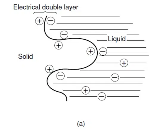
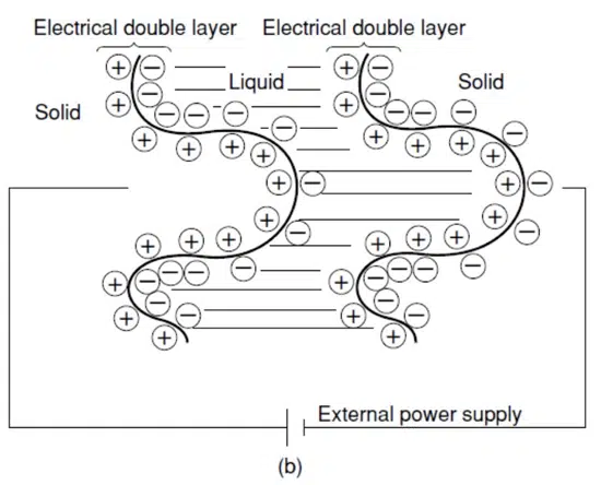
Figure 1 – The Principle of Electrical Double Layer Capacitors
Figure 2 shows a conceptual drawing of the basic structure of a supercapacitor using the electrical double layer principles.
A supercapacitor typically has a much higher capacitance than a conventional capacitor. However, the voltage ratings are very low because of how small the separation of charge is (typically less than 1nm, on the order of a single molecule diameter). Supercapacitors can be considered as the gap between electrolytic capacitors and batteries in terms of their characteristics and performance.
How EDLC Supercapacitors Work
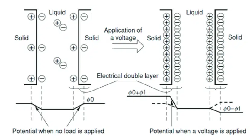
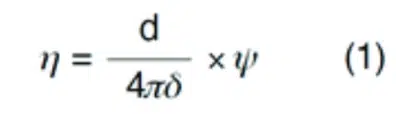
Suppose η is the amount of unitary charge of the solid part, d is the dielectric constant of the medium (liquid part), δ is the distance from the solid surface to the center of ions, and ψ is the potential of the double layer, then η is represented by expression (1).
According to Helmholtz’s theory, there is a potential gradient only in the electrical double layer, and their respective potential curves are shown in Figure 2. In Figure 2, if ψ and η are φ0 and η0, respectively, when no load is applied, then η0 is represented by expression (2).

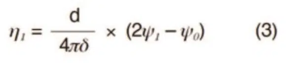
Then, if an external electrical field is applied, a charge is accumulated on the boundary surface shown in Figure 2. At this time, suppose ψ0 becomes ψ , and η0 becomes η1 , then η1 is represented by expression (3).
From expressions (2) and (3) above, expression (4) is found.
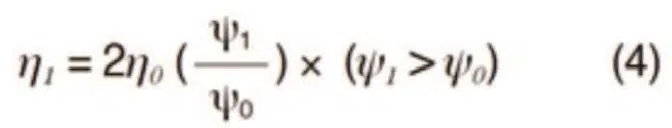
The external electrical field allows charge corresponding to η1 in expression (4) to accumulate in the electrical double layer. Here, ψ0 is on the order of several mV. According to an experiment using mercury for the electrode, an accumulated capacitance of 20 to 40 μF/cm2 per unit area is obtained. If the activated carbon electrode shows the same action as that of mercury, then activated carbon with a surface area of 1000 m2/g will produce a capacitance of 200 to 400 F/g. Such a high capacitance cannot be obtained in real life, however. KEMET’s proprietary technology has made it possible to obtain a value very close to the above value by improving the quality of the activated carbon surface and increasing specific surface area.
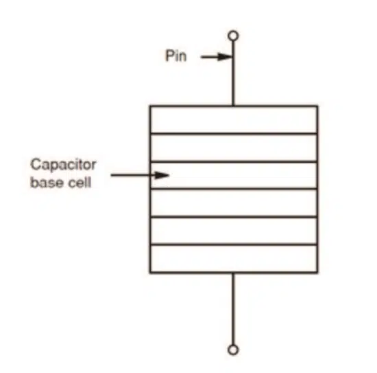
It is not possible to apply a voltage higher than an electrolyte’s decomposition voltage based on the substance that makes up an electrical double layer capacitor without damaging it. Therefore, it is necessary to structure the capacitor base cells in series to obtain the desired breakdown voltage.
The Structure of a Supercapacitor
Figure 3 shows the basic structure (capacitor base cell) of a supercapacitor.
The electrical double layer phenomenon appears on the boundary surface between activated porous carbon powder (solid) and the electrolyte, dilute sulfuric acid (liquid). The separator (porous organic film) has a structure that prevents short-circuit between the positive and negative electrodes (activated carbon powder). It lets ions pass in the electrolyte (dilute sulfuric acid).
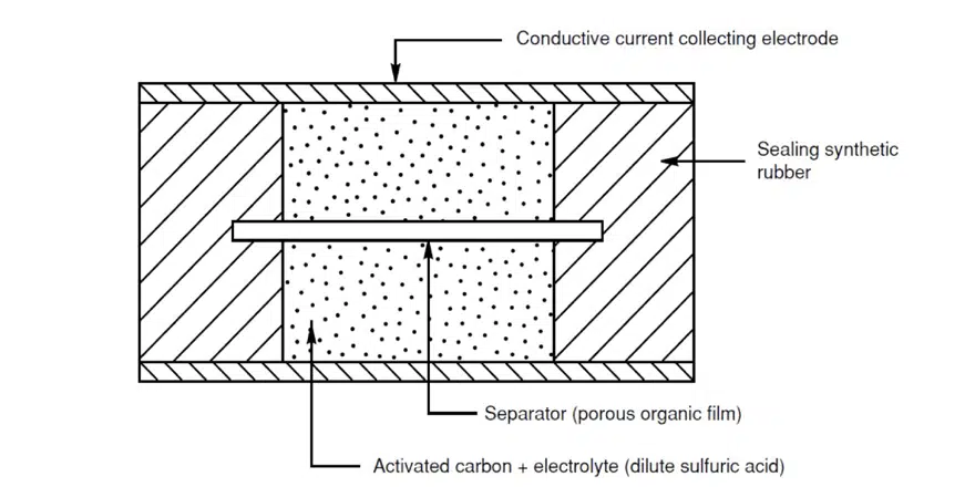
It also places a conductive current collecting electrode behind both electrodes (activated carbon powder), allowing a voltage to be applied to this capacitor base cell. In addition, it provides sealing rubber (mainly butyl rubber) at the electrode flank for sealing the electrolyte and isolating the conductive material. The amount of the electrolyte to be sealed into the capacitor base cell is equivalent to that needed for the impregnation of the pores inside activated carbon and the porous organic film, which is a minimal amount.
The breakdown voltage of the capacitor base cell depends on the electrolysis voltage of the electrolyte. The electrolysis voltage depends on the water content in the dilute sulfuric acid, which is approximately 1.2 V. To design the breakdown voltage for the maximum operating voltage of 5.5 V we must connect five or more sheets of capacitor base cells in series. (See Figure 4).
Pressure is applied inside the package to stabilize the electrical connection between the capacitor base cells, activated carbon powder particles, and conductive current collecting electrodes.
Automotive Grade Supercapacitors & Conclusion
KEMET’S Automotive Supercapacitor Devices
Unlike a battery, a supercapacitor stores and releases energy quickly through physical adsorption and ions’ desorption in the electrolyte between its electrodes. These processes are much faster than the chemical reactions involved in battery charging. Given the supercapacitor’s low internal resistance, it can fully charge within a few seconds. In contrast, a secondary cell can take from ten minutes to several hours to fully charge. Moreover, there is no theoretical limit to life cycle, whereas a lithium-ion secondary cell has a finite lifetime of about 500 cycles.
Modern advances in carbon-based materials enable porous electrodes to have a large surface area resulting in high capacitance values with small external dimensions.
The electrolyte also has an essential influence over device properties and typically is an organic compound. KEMET is the world’s only producer of supercapacitors that use aqueous electrolyte solutions. Dilute sulfuric acid electrolytes are highly conductive, have a low environmental impact, are non-toxic and non-flammable, and yield strong performance and safety credentials. They also typically have greater resistance to moisture absorption than organic compounds, resulting in a longer life with better stability.
For all device types, the electrolyte properties determine the overall supercapacitor terminal voltage. The voltage, when fully charged, is usually less than 3V.
A conventional approach to constructing supercapacitors is comparable to that of a coin cell battery, comprising lower and upper metal cases that are joined by swaging to enclose the carbon electrodes and organic electrolyte. Although an internal gasket aids in sealing, the electrolyte can dry within a relatively
short lifetime, and thermal shock can compromise structural integrity.
KEMET’s supercapacitors feature a high-strength vulcanized rubber bond that ensures high safety against liquid leakage. The cross-section of Figure 3 shows how these supercapacitors are constructed, including the dilute sulfuric acid electrolyte, rubberized electrodes, and separator membrane.
Several cells are connected in series to achieve the desired output voltage higher than the base voltage of a single cell. Coin- type supercapacitors, for example, are often stacked inside an external can or within a tube of heat-shrink material and electrodes attached to the upper and lower surfaces.
Supercapacitors containing a dilute sulfuric acid electrolyte can be stacked efficiently to achieve higher voltage ratings within smaller case sizes, with the added advantage of a strongly bonded seal to protect against thermal and mechanical shock.
This robust and reliable device from KEMET has been able to achieve the severe environmental resistance required by the automotive market.
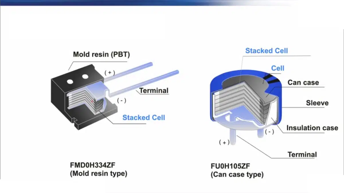
Figure 5 shows KEMET’s supercapacitor product, FMD0H105ZF. This high-capacity supercapacitor in a resin-molded package enables tape-and-reel packaging and is compatible with automatic mounting. It is the world’s first device to guarantee 1,000 hours in a high temperature and high humidity environment of 85°C-85% with a high breakdown voltage of 5.5V.
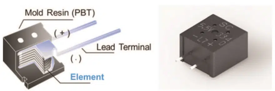
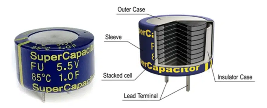
Figure 6 shows another KEMET product, FU0H105ZF. This device operates up to 5.5V, and the outer packaging is a sealed metal conventional can. This product is a long-life supercapacitor with a life of 4,000 hours at 85°C. This 4,000-hour life means that the product can be used in a wide range of applications. Four thousand hours at 85°C is equivalent to 10 years of life when referring to the mission profile near the dashboard of an automobile.
KEMET has paid special attention to cell materials to meet automotive requirements, which require high reliability. For the separator, highly heat-resistant material is used so that the pore diameter of the separator would not close even after extended use in a high-temperature environment.
In addition, the terminal material has been reviewed to improve resistance to high humidity and vibration. Those NPDs have a significant advantage in the resistance to moisture of the electrolyte under severe conditions (85°C/85% RH), one of the requirements for automotive use, as an example.
The FU0H105ZF realizes multi-stacking without increasing contact resistance due to KEMET’s unique cell stacking technology, achieving even higher reliability (85°C-5.5V 4000h) by reducing the voltage load per unit cell.
Due to their cell sealing structure and cell stacking technology, KEMET aqueous supercapacitors also have very high mechanical stress resistance in mechanical shock and vibration tests.
Reality and Lifetime of Supercapacitors
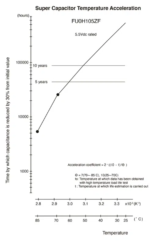
Figure 7 demonstrates that the FU0H105ZF has an effective lifetime of 5,300 hours at 85°C based on high-temperature load test data, beyond its guaranteed lifetime of 4,000 hours at 85°C.
Advantages of Supercapacitors in High Temp and High Humidity
A common problem for electrolytic capacitors is for the liquid electrolyte to dry up under high-temperature conditions. When the electrolyte dries out, capacitance decreases, and ESR increases. Similarly, KEMET’s supercapacitors form an electric double layer with the H+ and O- ions of water in dilute sulfuric acid, so the evaporation of these water ions under high-temperature conditions can lead to dry-up and a shortened lifetime.
However, KEMET’s electrolyte, which is dilute sulfuric acid, maintains high durability even under high temperature and high humidity conditions because of the water-absorbing properties of the sulfuric acid. It effectively replenishes water under high humidity conditions, which prevents dry-up.
Conclusion
Supercapacitors offer a high-performing alternative to batteries in a wide variety of backup-power applications, delivering far greater cycle life without the need for designers to worry about battery recharging or replacement.
The latest supercapacitors using KEMET’s aqueous electrolyte solution are effective energy storage devices with the high voltage, long life, and durability in harsh environments required by the automotive market.
KEMET’s new supercapacitors will be useful in the automotive, industrial, medical, and aerospace industries, along with any other fields requiring high-reliability performance for applications such as RTC hold-up and non-volatile memory backup.


