


This article provides basic overview of shunt current sense resistors, its typical characteristics, types and applications as a practical guide for accurate current measurement
Key Takeaways
- Shunt resistors are essential for accurate current measurement in power electronics, battery systems, and industrial controls.
- They convert current into a measurable voltage while minimizing power loss.
- Key parameters include resistance value, power rating, temperature coefficient, and tolerance.
- Different technologies, such as metal foil and wirewound, offer varying precision and power handling capabilities.
- Proper layout and thermal management are crucial for achieving precise measurements with shunt resistors.
Introduction
Shunt current sense resistors are the simplest and most widely used way to measure current in power electronics, battery systems and industrial controls. They convert current into a small, accurate voltage that can be digitized or fed into an amplifier, while adding minimal losses and cost to the design.
This article explains how shunt resistors work, what key parameters matter, and how to design them into real circuits. The focus is on practical selection, layout and error mechanisms rather than on theory alone.
Key features and benefits
Shunt resistors are precision low‑ohmic components used in series with the current path to generate a measurable voltage proportional to current. They follow Ohm’s law, where the current is obtained from the voltage drop across a known resistance value.
Typical characteristics of current sense shunts include:
- Very low resistance values from micro‑ohms to tens of milliohms to minimise power loss and self‑heating.
- Defined power ratings from fractions of a watt up to tens of watts to handle continuous and overload currents.
- Low temperature coefficient of resistance (TCR) to keep resistance stable across operating temperature.
- Construction options such as metal foil, metal film and wirewound, each with different TCR, power and inductance behaviour.
- Package types from small SMD chips to larger through‑hole shunts for high‑current bus bars and industrial systems.
In practice, these properties translate into precise, repeatable current measurements in a compact and cost‑effective form factor, provided that the resistor is correctly sized and thermally managed.
Basic operating principle
A shunt resistor is inserted in the current path so that the entire load current flows through it. The voltage drop across the resistor is then measured by a high‑impedance circuit (ADC, instrumentation amplifier or dedicated current‑sense IC) and converted into a current value.If the resistance is accurately known and stable, and the voltage can be measured with sufficient resolution, the resulting current reading can achieve high accuracy even with a small voltage drop.
Key electrical parameters
When selecting a shunt for current sensing, designers should pay attention to:
- Resistance value
- Low enough to keep power dissipation and losses acceptable.
- High enough to generate a measurable voltage (for example tens of millivolts at full‑scale current).
- Power rating
- Continuous power rating must exceed with adequate derating.
- Short‑term overload or pulse capability is important for fault, inrush or motor stall conditions.
- Temperature coefficient of resistance (TCR)
- Specified in ppm/°C; lower TCR reduces drift of resistance with temperature.
- Critical for high‑accuracy energy measurement and wide temperature range applications.
- Tolerance
- Tight initial tolerance (for example ±0.5% or better) reduces calibration effort.
- Some systems still perform software calibration and can tolerate looser initial tolerances.
- Parasitics (inductance and capacitance)
- Low inductance is essential for fast, high‑frequency current sensing and switching converters.
- Wirewound shunts may introduce significant inductance, while foil constructions achieve very low values.
- Operating temperature range
- The specified range should cover ambient plus self‑heating.
- In automotive or industrial equipment, this often runs from negative temperatures to well above 100 °C.
Shunt Resistors and Their Importance in Measuring Current
In modern electronics and power systems, accurate current measurement is essential for efficiency, safety, and control. One of the most reliable and cost-effective methods for current sensing is the use of shunt resistors. These precision components play a pivotal role in power monitoring systems across industries—from automotive and renewable energy to industrial automation and consumer electronics.
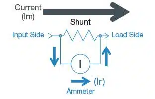
- Im: Total circuit flowing to the circuit
- Ir: Current flowing to the ammeter
- r: Internal electrical resistance of the ammeter
- R: Shunt (divide) resistance
For example, the total current (Im) flowing to the upper circuit can be expressed by the following equation.
Im = Ir + Ir × (r / R) = Ir × (1 + r / R)
As a result, the ratio of total current flowing through the circuit with the current flowing through the ammeter:
Im / Ir = (1 + r / R)
Why Use Shunt Resistors for Current Measurement?
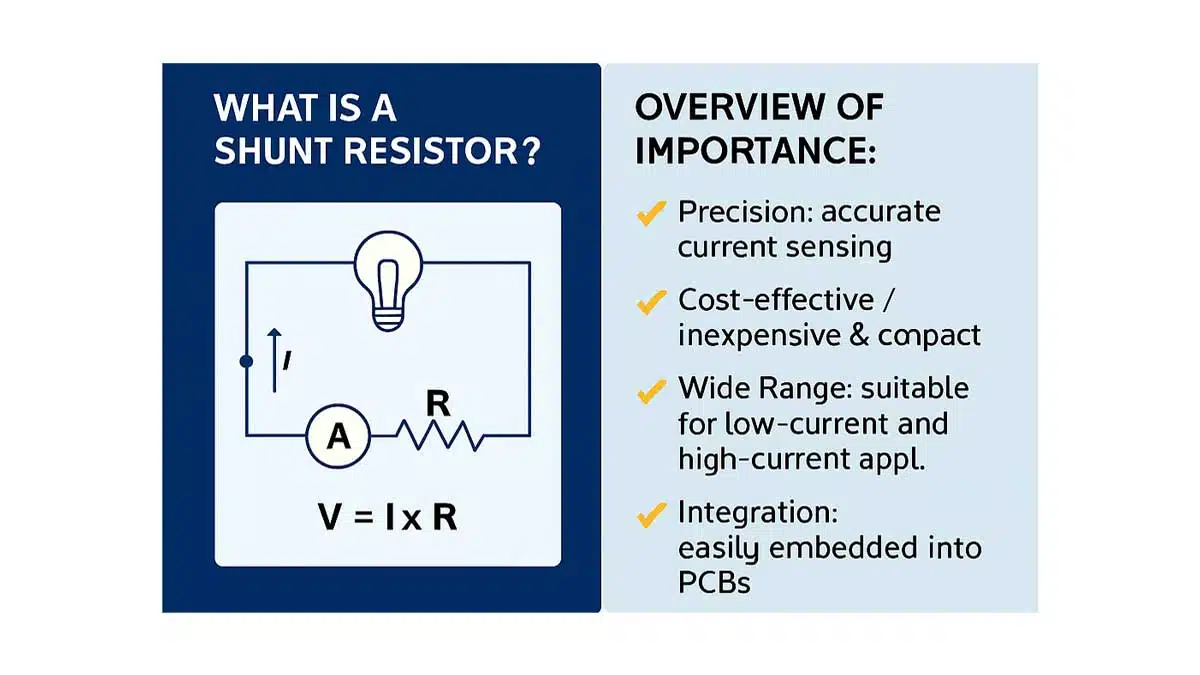
- Precision: Shunt resistors offer highly accurate current sensing when paired with precision ADCs or instrumentation amplifiers.
- Cost-Effective: Compared to Hall effect sensors or current transformers, shunt resistors are inexpensive and compact.
- Wide Range: Suitable for both low-current microampere measurements and high-current industrial applications.
- Integration: Easily embedded into PCBs and compatible with digital monitoring systems.
A simplified example of shunt datasheet parameters could look like:
| Parameter | Typical value | Practical implication |
|---|---|---|
| Resistance | 10 mΩ | Suitable for single‑digit ampere ranges |
| Power rating | 5 W | Handles several amps continuously |
| Resistance tolerance | ±0.5% | Allows precise current calculation |
| TCR | ±10 ppm/°C | Very low drift over temperature |
| Operating temperature range | −55 °C to +150 °C | Covers industrial and automotive environments |
| Maximum overload | 10× rated power, 5 s | Handles short‑term transients |
| Inductance | <10 nH | Suitable for switching converter current sense |
Exact values are always according to the manufacturer’s datasheet.
Shunt resistor technologies
The performance of shunt resistors depends heavily on their manufacturing processes. Common manufacturing techniques include:
- Metal Foil Technology: Involves bonding a thin metal foil with precision resistivity to a ceramic substrate. The process allows highly stable and low TCR resistors with excellent long-term reliability. The foil is carefully trimmed to achieve target resistance values and calibrated for accuracy. This method is preferred in precision applications.
- Metal Film Deposition: Metal films are sputtered or evaporated onto ceramic bases. The thickness and patterning of the film is controlled to set resistance. These resistors offer moderate precision and stability and are widely used for general purposes.
- Wirewound Construction: A resistive wire (often nickel-chrome) is wound tightly on a ceramic core. This type can handle high power ratings but may introduce inductance, limiting use in high-frequency circuits. Modern wirewound resistors employ special winding techniques to reduce inductance for certain applications.
- Laser Trimming: Post-manufacture, laser trimming is used for fine-tuning resistance values. This ensures very tight resistance tolerances and improves accuracy, especially important in precision shunts.
- Encapsulation and Coating: Resistors are coated and encapsulated to protect against moisture, oxidation, and mechanical damage. The quality of encapsulation affects stability and lifespan, particularly in harsh environments.
- Quality Control and Testing: Manufacturing includes rigorous testing for resistance accuracy, TCR, power rating, and thermal stability. Automated test setups provide traceability and ensure compliance with international standards.
Different construction technologies offer trade‑offs between power handling, precision, cost and frequency behaviour.
| Type | Resistance range | Power rating | TCR (ppm/°C) | Inductance | Typical use cases |
|---|---|---|---|---|---|
| Metal foil | ~1 μΩ to 100 mΩ | ~0.5 W to 10 W | ~±5 to ±20 | Very low | Precision current sensing, BMS, metering |
| Metal film | ~1 mΩ to 1 Ω | ~0.25 W to 5 W | ~±50 to ±100 | Low | General purpose current measurement |
| Wirewound | ~0.1 Ω to 10 Ω and above | ~5 W to 50 W+ | ~±100 to ±250 | Moderate to high | High power circuits, motor drives, loads |
Metal foil shunts are preferred where high accuracy and low inductance are critical. Metal film devices offer a good compromise for general applications. Wirewound designs are robust for high power, but their inductance limits suitability in fast switching or high‑frequency circuits.
Applications of Shunt Resistors
Shunt resistors are crucial components in a variety of applications:
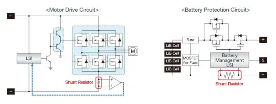
- Power Supplies and Inverters: Used for monitoring load currents in DC and AC power supplies, enabling precise regulation and protection.
- Battery Management Systems (BMS): Provide accurate charge and discharge current measurements in electric vehicles and renewable energy storage, ensuring battery health and safety.
- Overcurrent Protection: Detects when current exceeds set thresholds to trigger protective shutdowns, preventing damage to circuits and devices.
- Energy Meters: Measures consumption in residential and commercial electricity metering systems based on current flow monitored via shunt resistors.
- Motor Control: Enables feedback control by measuring motor current to optimize performance and efficiency.
- Testing and Laboratory Equipment: High-precision shunts are used in calibration and test instruments where accurate current measurement is critical.
- Industrial Automation: Facilitates real-time current sensing in automated manufacturing processes for monitoring and control.
Applications in Power Monitoring Systems
Shunt resistors are integral to power monitoring systems, enabling real-time tracking of current, power consumption, and energy usage. Key applications include:
- Battery Management Systems (BMS): Monitoring charge/discharge currents in EVs and portable electronics.
- Smart Meters: Measuring household or industrial energy consumption with high resolution.
- Power Supplies: Ensuring load regulation and overcurrent protection in DC/DC converters and inverters.
- Renewable Energy: Tracking current flow in solar inverters and wind turbine controllers.
Design‑in notes for engineers
This section focuses on practical steps and considerations when designing current sense shunts into a PCB.
Choosing the shunt value and power rating
When selecting a shunt resistor, engineers must consider:
- Resistance Value: Low enough to minimize power loss, but high enough to produce a measurable voltage.
- Power Rating: Must handle the expected current without overheating.
- Temperature Coefficient: Affects accuracy under varying thermal conditions.
- Mounting Style: Surface-mount vs. through-hole depending on application and thermal management.
Shunt resistors are indispensable tools in the realm of current measurement and power monitoring. Their simplicity, precision, and adaptability make them a cornerstone of modern electronic design. As energy efficiency and system intelligence become increasingly critical, the role of shunt resistors will only grow in importance.
A practical design flow for low‑side current sensing might be:
- Define the maximum continuous current and any short‑term overload or fault currents.
- Choose a target full‑scale voltage drop across the shunt at For many systems this is tens of millivolts (for example 50 mV or 100 mV) to balance resolution against power loss.
- Compute the nominal resistance .
- Compute continuous power dissipation and select a shunt with adequate power rating and derating margin.
- Check overload and pulse behaviour against worst‑case scenarios such as inrush, short circuits or motor stalls.
Quick Tip
For high-side current sensing, consider using a differential amplifier or dedicated current-sense IC to accurately measure the voltage across the shunt without disturbing the ground reference.
Designers should also ensure that the ADC or current‑sense amplifier input range matches the expected voltage across the shunt, including worst‑case tolerances and overloads.
High‑side versus low‑side current sensing
Shunt resistors can be placed either on the low‑side (between load and ground) or on the high‑side (between supply and load). Each approach has specific implications:
- Low‑side sensing
- Simpler measurement, often with the sense circuit referenced directly to ground.
- Ground potential of the load is shifted slightly by the shunt voltage, which may be an issue for sensitive circuits.
- Typically lower common‑mode voltage at the sense amplifier.
- High‑side sensing
- Maintains the load at a stable ground reference.
- Sense circuit must handle the full supply voltage as common‑mode; often uses a differential or dedicated current‑sense amplifier.
- Better suited for fault detection at the supply node and for systems where ground integrity is critical.
A quick rule of thumb: low‑side shunts are easier where small ground shifts are acceptable, while high‑side shunts are preferred for safety, supply monitoring and many automotive and industrial applications.
PCB layout and Kelvin sensing
For accurate measurements, layout is as important as the shunt component itself:
- Place the shunt close to the current path it monitors, ideally between the main supply and the load or between load return and system ground.
- Use wide copper traces and generous copper area to spread heat and keep additional series resistance low.
- Use Kelvin (four‑terminal) connections where possible: separate pads or dedicated terminals for the sense traces, routed from the inner region of the shunt pads rather than from the high‑current ends.
- Route sense traces as a tightly coupled pair directly to the measurement IC or ADC input, avoiding high‑current loops and noisy switching nodes.
- Avoid sharing vias or copper segments between the sense path and large load currents, which can introduce additional, uncontrolled resistance and inductance.
Even with two‑terminal shunts, PCB layout can emulate a Kelvin connection by placing the sense trace take‑off points close to the body of the shunt and away from high‑current entrances.
Thermal and accuracy considerations
Accuracy is influenced by tolerance, TCR, self‑heating and the measurement electronics. Important points include:
- Power dissipation in the shunt will raise its temperature; the resulting resistance increase depends on TCR and must be considered in the error budget.
- The PCB acts as a heatsink, so copper area, thermal vias and board material affect operating temperature.
- Datasheet derating curves for power versus ambient temperature or PCB size should be followed rather than relying solely on the nominal power rating.
- Sense amplifiers contribute offset and gain errors; ADCs add quantisation and reference errors. The total current measurement error is the sum of resistor and electronics contributions.
- For high‑precision systems such as energy metering, calibration at one or more operating points is often used to correct residual errors.
For dynamic or high‑frequency measurements, the inductance of the shunt and associated layout can limit bandwidth and cause distortion in fast current transients. Low‑inductance constructions and careful routing are recommended in switching converters and fast motor drives.
When a shunt is not the best choice
Although shunts are the default choice for many designs, there are situations where other technologies may be more suitable:
- Very high voltages where the required common‑mode range would exceed available amplifiers or pose safety concerns.
- Applications requiring galvanic isolation between measurement and power domains.
- Strong magnetic or EMI environments in which long sense leads or poor layout would introduce unacceptable noise or offset.
- Extremely high currents where the required shunt power rating and copper area become impractical.
In these cases, Hall effect sensors or current transformers may complement or replace shunt‑based sensing.
Conclusion
Shunt current sense resistors provide a straightforward, accurate and cost‑effective way to measure current in power electronics, battery systems, industrial automation and many other applications. With appropriate selection of resistance, power rating and technology, combined with correct layout and thermal design, they can deliver precise measurements over wide current and temperature ranges.
For engineers and purchasing specialists, understanding the trade‑offs between different shunt technologies, mounting options and electrical parameters helps to ensure that the selected device meets both performance and cost requirements. When combined with suitable current‑sense amplifiers or ADCs, shunt resistors remain a cornerstone of modern current sensing and power monitoring.
Further Read:
FAQ: Shunt Resistors for Current Measurement
A shunt resistor is a low-resistance precision component placed in series with a load to measure current. When current flows through it, a small voltage drop is generated, which can be measured and converted into a current value using Ohm’s law.
The shunt resistor produces a voltage drop proportional to the current according to V = I × R. By accurately measuring this voltage with a meter, ADC or current-sense amplifier and knowing the precise resistance value, the current in the circuit can be calculated with high accuracy.
Shunt resistors are simple, compact and cost-effective, offering high accuracy over a wide current range. They integrate easily on PCBs and work well with precision ADCs or instrumentation amplifiers, making them suitable for many power monitoring and control applications.
Important parameters include resistance value (typically micro-ohms to milliohms), power rating, temperature coefficient of resistance (TCR), tolerance, material type (metal foil, metal film, wirewound), physical size and thermal management. These determine accuracy, power dissipation and long-term stability.
Shunt resistors are used in power supplies and inverters, battery management systems, energy meters, motor drives, industrial automation and laboratory test equipment. They enable real-time current measurement for regulation, protection and energy monitoring.
Common materials include metal foil and metal film for precision, low-TCR applications, and wirewound constructions for high power handling. All are typically based on alloys such as manganin or constantan to achieve low TCR and stable resistance over temperature.
Limitations include self-heating due to power dissipation, the need for sensitive voltage measurement circuits because of low resistance values, and parasitic inductance or capacitance in some constructions. Poor layout and wiring can also introduce additional errors through contact resistance and lead inductance.
Metal foil shunts offer the lowest TCR and inductance for high-precision sensing. Metal film shunts are a good general-purpose choice with moderate precision. Wirewound shunts handle high power but have higher inductance, which can limit their use in high-frequency or fast-switching circuits.
How-to: Design a Basic Current Measurement Circuit with a Shunt Resistor
- Step 1: Define the current range and measurement purpose
Start by specifying the maximum continuous current you need to measure and the application, for example load current monitoring in a power supply, battery pack or motor drive. Decide whether the measurement is for regulation, protection, energy metering or simple diagnostics, as this will influence required accuracy and cost.
- Step 2: Choose the target shunt voltage drop
Select a target full-scale voltage drop across the shunt at maximum current, typically in the range of a few tens of millivolts. The drop must be high enough for your ADC or measuring circuit to resolve accurately, but low enough to minimise power loss and avoid disturbing the circuit operation.
- Step 3: Calculate the required shunt resistance
Use the relation R = V / I with your chosen full-scale voltage and maximum current to calculate the nominal shunt resistance. For example, a 50 mV drop at 10 A requires a 5 mΩ shunt, which provides a measurable signal with limited extra losses in the current path.
- Step 4: Check power dissipation and select power rating
Calculate the power dissipated in the shunt using P = I² × R at maximum current. Compare this with available shunt power ratings and choose a component with adequate margin, allowing for derating over ambient temperature and PCB conditions to avoid excessive self-heating.
- Step 5: Select technology, tolerance and TCR
Choose a shunt technology (metal foil, metal film or wirewound) based on required accuracy, frequency behaviour and power level. Specify tolerance and TCR values that match your error budget; high-precision or metering applications benefit from low TCR and tight tolerance to minimise drift and calibration effort.
- Step 6: Decide on low-side or high-side placement
Determine whether the shunt should be placed in the low-side return path or in the high-side supply line. Low-side placement simplifies measurement but slightly shifts the load ground, while high-side placement maintains ground reference and may require a differential or dedicated current-sense amplifier with suitable common-mode range.
- Step 7: Lay out the PCB for accurate sensing
Place the shunt close to the current path and use wide copper areas to carry the main current and spread heat. Route separate sense traces from the inner region of the shunt pads (Kelvin connection) directly to the measurement circuit, avoiding shared vias and noisy high-current loops to reduce additional resistance and inductance.
- Step 8: Verify accuracy and thermal behaviour
Simulate or calculate the expected temperature rise of the shunt and its effect on resistance using the specified TCR. Combine shunt tolerance, TCR, self-heating and measurement electronics errors into an overall error budget, and, if necessary, perform calibration at one or more operating points to meet your accuracy target.


