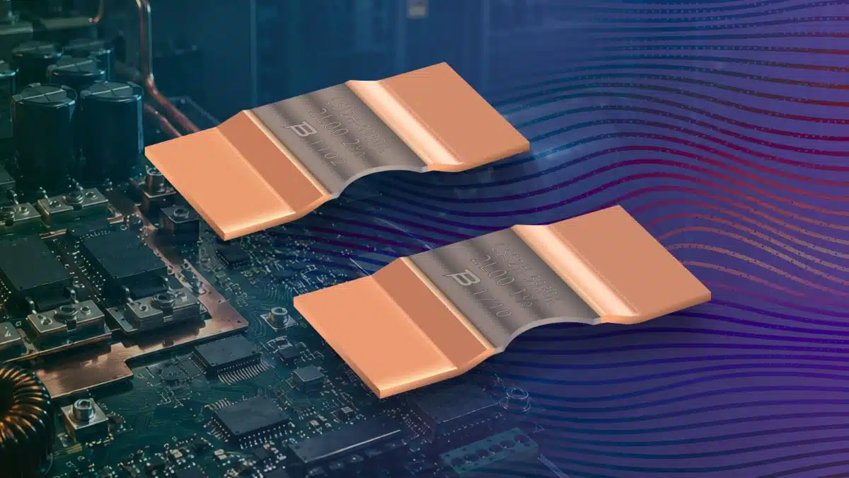
Bourns has extended its CSS2H-5930 and CSI2H-5930 current sense resistor families with 0.1 mΩ models rated at 15 W.
The ultra-low-resistance SMD shunts target applications where high current must be measured with minimal insertion loss, low inductance and controlled thermal drift.
The new devices use an electron-beam-welded metal-strip construction. In practice, the 0.1 mΩ value reduces the sense-voltage burden and dissipation in demanding battery, converter and industrial power paths, while still providing a measurable signal for an appropriate current-sense amplifier or ADC.
Key features and benefits
- 0.1 mΩ resistance and 15 W rating: This combination is intended for high-current paths where a conventional milliohm-range resistor would create excessive voltage drop and heat.
- Low inductance: Bourns specifies less than 3 nH for Material Type R, supporting use in switching power stages and control loops where fast current transients must be measured with limited parasitic effects.
- Electron-beam-welded metal-strip element: The construction is specified to provide low resistance, low thermal EMF and long-term stability.
- Low TCR alloy: The resistive alloy is specified at ±50 ppm/°C from 20 °C to 60 °C, helping reduce resistance drift caused by changing operating temperature.
- Wide operating-temperature range: Both new models are rated from −55 °C to +170 °C.
- Automotive option: The CSS2H-5930R-L100x is stated to be AEC-Q200 compliant and automotive grade, making it relevant for qualified vehicle electronics programmes.
- Environmental compliance: Bourns specifies RoHS compliance and halogen-free construction for the series.
A current sense shunt resistor converts load current into a small voltage drop. At very low resistance values, the practical design trade-off shifts toward measurement-chain offset, layout resistance and thermal gradients rather than simple resistor dissipation alone.
Technical highlights
| Parameter | CSS2H-5930R-L100x | CSI2H-5930R-L100x |
|---|---|---|
| Resistance value | 0.1 mΩ | 0.1 mΩ |
| Power rating at 70 °C | 15 W | 15 W |
| Operating temperature | −55 °C to +170 °C | −55 °C to +170 °C |
| Resistive-alloy TCR, 20 °C to 60 °C | ±50 ppm/°C | ±50 ppm/°C |
| TCR including copper terminals, 20 °C to 60 °C | ±275 ppm/°C | ±275 ppm/°C |
| Inductance, Material Type R | <3 nH | <3 nH |
| Resistance tolerance | ±1%, ±5% | ±1%, ±2%, ±5% |
| Automotive qualification | AEC-Q200 compliant, automotive grade | Not stated |
The difference between the alloy-only TCR and the TCR including copper terminals is important in sub-milliohm sensing. At 0.1 mΩ, terminal and PCB interconnect contributions can become a meaningful part of the total measurement error, particularly where current and temperature vary widely.
For a nominal 0.1 mΩ shunt, 100 A produces a 10 mV sense voltage and dissipates 1 W. At 300 A, the nominal voltage is 30 mV and dissipation is 9 W; final suitability still depends on the manufacturer’s derating data, PCB copper area, airflow, ambient temperature and overload conditions.
Typical applications
Bourns identifies the new 0.1 mΩ variants for:
- Current sensing in high-current power paths
- Battery management systems, specifically for the CSS2H-5930R-L100x
- Power modules
- Frequency converters
- Industrial power systems
- Voltage-divider functions where the electrical and power requirements are appropriate
The combination of a 15 W rating and sub-milliohm resistance is particularly relevant to battery charge/discharge monitoring, inverter phase-current measurement, motor drives, power-distribution monitoring and DC/DC converter protection functions.
Application fit
| Design environment | Why the 0.1 mΩ option may fit | Main verification priority |
|---|---|---|
| Battery management system | Low loss in high-current charge and discharge paths; automotive-qualified CSS2H option | Full error budget across temperature, current range and connector/copper resistance |
| Inverter or frequency converter | Low parasitic inductance supports fast switching-current measurement | Pulse performance, layout-induced noise and sense-amplifier bandwidth |
| Industrial power module | 15 W rating supports comparatively high continuous current with low burden voltage | Thermal spreading through PCB copper and system-level derating |
| Power-distribution monitoring | Low voltage drop helps preserve rail efficiency | ADC resolution and amplifier offset at low sense voltages |
Design-in notes for engineers
- Calculate the real operating point: Use P=I2R for continuous dissipation, then apply the datasheet derating conditions. A 15 W nominal rating is not a substitute for checking the actual board-level thermal environment.
- Account for low sense voltage: A 0.1 mΩ resistor produces only millivolt-level signals at many operating currents. Confirm that amplifier offset, gain error, ADC resolution and reference accuracy meet the required current-measurement error budget.
- Use Kelvin sense routing: Route the voltage-sense pair from the inner edges of the resistor pads, separately from the high-current copper path. This is essential because milliohm and sub-milliohm measurements are easily distorted by trace and solder-joint voltage drops.
- Keep the thermal environment symmetrical: Unequal heating of terminals, copper pours or nearby switching devices can add thermal EMF and resistance-related offset. Avoid placing sensitive sense traces near hot MOSFETs, inductors or switching nodes.
- Check the complete temperature coefficient: The specified alloy TCR is only one contributor. For board-level accuracy, include the stated terminal-inclusive TCR, copper resistance and self-heating in the calculation.
- Validate transient conditions: Evaluate start-up, battery fault, inrush, motor stall and short-circuit events against the manufacturer’s pulse and overload data according to the manufacturer datasheet.
- Select tolerance deliberately: CSS2H offers ±1% and ±5% options, while CSI2H adds ±2%. Tighter initial tolerance can reduce calibration requirements, but it does not eliminate temperature-related and layout-related errors.
- Confirm qualification status by exact part number: Bourns specifically identifies CSS2H-5930R-L100x as AEC-Q200 compliant and automotive grade. Do not extend that statement to other variants without checking the current manufacturer documentation.
For additional layout and error-budget guidance, see Overcoming the Challenges of Using Sub-Milliohm SMD Current Sense Chip Resistors.
Further reading
- Current Sense Shunt Resistor
- How to Choose Current Sense Resistor
- Current Sense Resistor Selection Tradeoffs
- Performance of AEC-Q200 Rated Power Resistors for Automotive Use
Source
This article is based on the Bourns manufacturer press release covering the CSS2H-5930 and CSI2H-5930 Series extensions. Engineers should consult the current manufacturer datasheet, derating curves, ordering information and qualification documentation before final component selection and design release.