Passive Components Blog
No Result
View All Result
  • Home
  • NewsFilter
    • All
    • Aerospace & Defence
    • Antenna
    • Applications
    • Automotive
    • Capacitors
    • Circuit Protection Devices
    • electro-mechanical news
    • Filters
    • Fuses
    • Inductors
    • Industrial
    • Integrated Passives
    • inter-connect news
    • Market & Supply Chain
    • Market Insights
    • Medical
    • Modelling and Simulation
    • New Materials & Supply
    • New Technologies
    • Non-linear Passives
    • Oscillators
    • Passive Sensors News
    • Resistors
    • RF & Microwave
    • Telecommunication
    • Weekly Digest

    ECIA Industry Pulse April 2026: Sentiment Cools but Stays Strong

    Industrial Passive Components Markets and Technologies 2026

    Automotive Passive Components Technology Dossier

    Samsung Electro-Mechanics Signs 1.5T KRW Silicon Capacitor AI Contract

    Murata Expands Thermistor Production Capacity at Yokaichi Plant

    Hirose Expands Compact High‑Voltage EV connectors

    Qi2 Wireless Charging: Inductors, Capacitors and EMC Filters

    Samsung Introduced Low ESL 3-Terminal Reverse-Geometry MLCCs for High-Performance ADAS

    Würth Elektronik Presents New Bidirectional Digital Isolators

    Trending Tags

    • Ripple Current
    • RF
    • Leakage Current
    • Tantalum vs Ceramic
    • Snubber
    • Low ESR
    • Feedthrough
    • Derating
    • Dielectric Constant
    • New Products
    • Market Reports
  • VideoFilter
    • All
    • Antenna videos
    • Capacitor videos
    • Circuit Protection Video
    • Filter videos
    • Fuse videos
    • Inductor videos
    • Inter-Connect Video
    • Non-linear passives videos
    • Oscillator videos
    • Passive sensors videos
    • Resistor videos

    Qi2 Wireless Charging: Inductors, Capacitors and EMC Filters

    Two‑capacitor paradox explained for engineers

    Capacitances of Nonlinear MLCCs: What Datasheets Don’t Tell You

    Tapped Inductor Buck Converter Fundamentals

    Planar vs Conventional Transformer: When it Make Sense

    Modeling Fringing Field Losses in Inductors & Transformers

    Why Power Inductors Use a Ferrite Core With an Air Gap

    Transformer-Based Power-Line Harvester Magnetic Design

    Thermal Modeling of Magnetics

    Trending Tags

    • Capacitors explained
    • Inductors explained
    • Resistors explained
    • Filters explained
    • Application Video Guidelines
    • EMC
    • New Products
    • Ripple Current
    • Simulation
    • Tantalum vs Ceramic
  • Knowledge Blog
  • DossiersNew
  • Suppliers
    • Who is Who
  • PCNS
    • PCNS 2025
    • PCNS 2023
    • PCNS 2021
    • PCNS 2019
    • PCNS 2017
  • Events
No Result
View All Result
Passive Components Blog
No Result
View All Result

Capacitors Cooling Explained

18.12.2024
Reading Time: 5 mins read
A A
Aluminum electrolytic capacitor with heatsink. Image courtesy of TDK

Aluminum electrolytic capacitor with heatsink. Image courtesy of TDK

Cooling a capacitor helps to enhance its performance as well as its reliability. Cooling will extend its life; taking away more heat from the capacitor can also give it more power-carrying ability. Murray Slovick dig into more details of methods and principles how to cool capacitors in his article published by TTI Market Eye.

Capacitors have resistance in their electrodes and dielectrics. This resistance generates heat when AC current like ripple current – a periodic non-sinusoidal waveform derived from an AC power source – passes through.

RelatedPosts

ECIA Industry Pulse April 2026: Sentiment Cools but Stays Strong

Industrial Passive Components Markets and Technologies 2026

Automotive Passive Components Technology Dossier

Capacitors are rated for ripple current and exceeding the ripple current rating will increase internal heating, limit the overall reliability of the device and reduce the capacitor’s lifetime. High ripple current and high temperature of the environment in which the capacitor operates causes heating due to power dissipation. High temperatures can also cause hot spots within the capacitor and can lead to its failure.

Methods of Cooling Capacitors

The most common cooling methods include self-cooling, forced ventilation and liquid cooling. The simplest method for cooling capacitors is to provide enough air space around the capacitor so it will stay sufficiently cool for most applications.

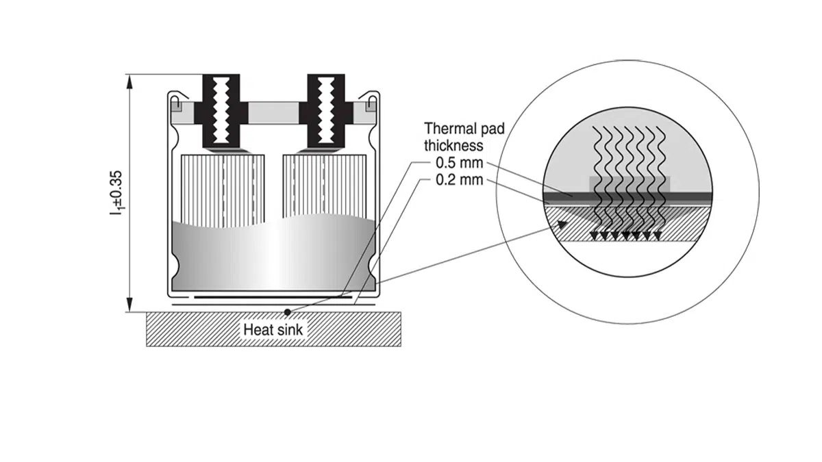
“Most applications,” but not all. In many designs and installations self-cooling through natural air circulation simply cannot cool capacitors adequately. In higher power cases, the larger heat load may require additional cooling by means of an external heat dissipator or heat sink (not unknown, but not common with capacitors since they take up a lot of space); a fan, which can forcefully direct cooling air over the capacitor; or liquid cooling. Water-cooled capacitors are usually employed in applications such as induction heating, melting or annealing, as well as in high-frequency welding systems.

Here, losses in the form of heat are desirable. Induction heating, a controlled and contactless method of heating, takes place when an electrically conductive material is placed within a variable magnetic field. Induction heating finds applications in many industries for forging, welding, sealing, etc.

Induction heating is ideal for automated production lines and controlled environments – for example, the automotive industry uses induction for heat-treating a variety of chassis and drivetrain parts.

As induction heating experts will note, installing the proper cooling system will extend the life of an induction power supply, reducing maintenance costs and downtime. A typical induction heater system includes a power supply, impedance matching circuit, tank circuit and applicator. Choosing proper capacitance for the resonant circuit is important in designing a resonant induction heating system: the capacitance affects the resonant frequency, output power, ESR, Q-factor, heating efficiency and power factor.

The resonance tank in an induction heating system is normally a parallel set of capacitor and inductor which resonates at a certain frequency. A bank of capacitors provides the needed capacitance in order to reach a resonance frequency matching the capability of the power supply. The inductor is the source of electromagnetic energy.

In these applications, the system’s capacitors can reach temperatures that require liquid cooling. These water–cooled capacitors are specially designed for use in inductive heating and melting plants for power factor improvement and also for tuning of the circuits for varying inductive loads. The liquids that are commonly used in such systems are water, a mixture of water and chemical solutions, and de-ionized water.

As Anthony Kenny states in his article on the subject, “Most traditional cooling systems are designed to cool a capacitor by passing the cooling medium over the external casing of the component.” However, such methods of cooling (which only bring the cooling medium into contact with the external case of the capacitor) are not as efficient thermally as the designs of water-cooled capacitors where water is passed through the interior of the capacitor so that heat is extracted as close as possible to its where it is generated. In most modern water-cooled capacitors, the cooling medium passes through the interior of the component.

The cooling conditions in place will help determine the performance and operating lifespans of these water-cooled capacitors.

An Environmentally Correct Cooling System

Now that we’ve spent some time reviewing methods aimed at ensuring that the temperature of a capacitor is maintained within acceptable limits, let’s move on to an emerging capacitor-based technology that is showing promise as a “green” cooling agent.

Designs for what is known as electrocaloric (EC) cooling use materials that change temperature under an electric field, leading to a temperature difference between the hot side and the cold side. Multilayer ceramic chip capacitors (MLCCs) are promising EC cooling elements because they operate at low voltages, possess large breakdown fields, contain inner electrodes that facilitate heat transfer and exhibit sufficiently active EC material.

As Xavier Moya et al. note in their research, “the observation of electrocaloric effects in commercial multilayer capacitors has inspired the possibility of environmentally friendly cooling.” This type of cooling system boasts increased efficiency, with few or no moving parts and without the need for refrigerants that harm the environment or pose a fire hazard.

What is more, EC multilayer ceramic capacitors can be fabricated in a manufacturing-compatible process. Recently, a group of scientists from Xerox Parc described in the journal Science an EC cooling material employing lead, scandium and tantalum (PST) in multilayer ceramic capacitors that change temperature under an electric field.

These researchers obtained a system temperature span of 5.2 degrees C and a maximum heat flux of 135 milliwatts per square centimeter. They used a large-volume fabrication technique often employed in the electronics industry to produce a device from MLCCs that, the scientists say, shows how lab-scale devices that change temperature under an electric field could be scaled up.

When they applied an electric field of 10.8 MV/m, the capacitors underwent an adiabatic temperature rise (and fall) of 2.5 degrees C per cycle at room temperature. With the cold sink steadily cooling over the course of about 100 cycles, its temperature dropped by up 5.2 degrees C compared with the hot sink.

According to the researchers, the measured heat flux was reported to be more than four times higher than other EC cooling demonstrations, and the temperature lift was among the highest for EC systems that use ceramic multilayer capacitors, according to the researchers.

The device invented by the research team isn’t fully solid state. The electrocaloric effect involves alternately applying and removing an electric field to the material to increase and decrease the material’s temperature, respectively. The PARC device has two layers of multi-layer capacitors lined up between copper rails and separated by insulators. The upper layer contains five capacitors, while the lower one has four and is capped by an aluminum heat sink at each end.

The device physically moves the capacitors back and forth between hot and cold regions to effect cooling. An actuator moves the top layer so that its capacitors are always aligned with those below, while an extra capacitor at either end comes into and out of thermal contact with the heat sink below it. Repeating this process results in cooling.

Multilayer capacitors of PST have been demonstrated to be well-suited for cooling applications. With further development, one day these electrocaloric cooling devices may even replace today’s refrigerators and air conditioners.

Related

Source: TTI Market Eye

Recent Posts

Industrial Passive Components Markets and Technologies 2026

21.5.2026
14

Automotive Passive Components Technology Dossier

21.5.2026
18

Samsung Electro-Mechanics Signs 1.5T KRW Silicon Capacitor AI Contract

21.5.2026
12

Qi2 Wireless Charging: Inductors, Capacitors and EMC Filters

21.5.2026
17

Samsung Introduced Low ESL 3-Terminal Reverse-Geometry MLCCs for High-Performance ADAS

20.5.2026
28

Using Stress–Strain Curves to Diagnose Tantalum Powders for Capacitors

20.5.2026
24

Samsung Launches Ultra-Compact 008004 High Q MLCC for Next-Generation RF Applications

20.5.2026
21

Nichicon Extends Rechargeable Batteries Temperature to Rival Supercapacitors

19.5.2026
26

Two‑capacitor paradox explained for engineers

18.5.2026
53

Upcoming Events

Jun 2
16:00 - 17:00 CEST

Calculation, Simulation and Measurement of 800V EMC Filters

Jun 16
16:00 - 17:00 CEST

EMC with EMC – EMC‑compliant design with electromechanical connectors

View Calendar

Popular Posts

  • Buck Converter Design and Calculation

    0 shares
    Share 0 Tweet 0
  • Boost Converter Design and Calculation

    0 shares
    Share 0 Tweet 0
  • Flyback Converter Design and Calculation

    0 shares
    Share 0 Tweet 0
  • LLC Resonant Converter Design and Calculation

    0 shares
    Share 0 Tweet 0
  • MLCC and Ceramic Capacitors

    0 shares
    Share 0 Tweet 0
  • Capacitor Charging and Discharging

    0 shares
    Share 0 Tweet 0
  • What Electronics Engineer Needs to Know About Passive Low Pass Filters

    0 shares
    Share 0 Tweet 0
  • Dual Active Bridge (DAB) Topology

    0 shares
    Share 0 Tweet 0
  • Ripple Current and its Effects on the Performance of Capacitors

    3 shares
    Share 3 Tweet 0
  • Samsung Electro-Mechanics Releases High-Capacitance MLCCs for AI Server Applications

    0 shares
    Share 0 Tweet 0

Newsletter Subscription


Passive Components Blog

© EPCI - Leading Passive Components Educational and Information Site

  • Home
  • Privacy Policy
  • EPCI Membership & Advertisement
  • About

No Result
View All Result
  • Home
  • Knowledge Blog
  • Dossiers
  • PCNS

© EPCI - Leading Passive Components Educational and Information Site

This website uses cookies. By continuing to use this website you are giving consent to cookies being used. Visit our Privacy and Cookie Policy.
Go to mobile version