Passive Components Blog
No Result
View All Result
  • Home
  • NewsFilter
    • All
    • Aerospace & Defence
    • Antenna
    • Applications
    • Automotive
    • Capacitors
    • Circuit Protection Devices
    • electro-mechanical news
    • Filters
    • Fuses
    • Inductors
    • Industrial
    • Integrated Passives
    • inter-connect news
    • Market & Supply Chain
    • Market Insights
    • Medical
    • Modelling and Simulation
    • New Materials & Supply
    • New Technologies
    • Non-linear Passives
    • Oscillators
    • Passive Sensors News
    • Resistors
    • RF & Microwave
    • Telecommunication
    • Weekly Digest

    Würth Elektronik Expands Nanocrystalline Cable Cores for Broadband EMI Suppression

    High‑Speed Supercapacitor Balancing for AI Data Center Power Systems

    Bourns Introduced Automotive TVS Diodes for Compact ESD Protection

    EMC‑Compliant PCB and Connector Design Guidelines

    Practical Value of Structural Diagnostics for Tantalum Capacitor Anodes

    Hall-Effect Sensing for Harsh Environments: TT Electronics Selected in NASA’s Dragonfly Fan

    Bourns Releases Automotive Gate Driver Transformer for Isolated Power

    Stackpole Releases High-Frequency Thin Film Chip Resistors for RF up to 50 GHz

    Knowles Expands High‑Q Ceramic Core Inductors for RF designs

    Trending Tags

    • Ripple Current
    • RF
    • Leakage Current
    • Tantalum vs Ceramic
    • Snubber
    • Low ESR
    • Feedthrough
    • Derating
    • Dielectric Constant
    • New Products
    • Market Reports
  • VideoFilter
    • All
    • Antenna videos
    • Capacitor videos
    • Circuit Protection Video
    • Filter videos
    • Fuse videos
    • Inductor videos
    • Inter-Connect Video
    • Non-linear passives videos
    • Oscillator videos
    • Passive sensors videos
    • Resistor videos

    EMC‑Compliant PCB and Connector Design Guidelines

    Why Isolated DC/DC Power Supplies Fail Late, Würth Elektronik Podcast

    Designing 800 V DC EMC Filters: Calculation, Simulation and Measurement

    Current Sense Transformer Datasheet and Design‑in Guide

    Designing a USB Type‑C Flyback Planar Transformer with Frenetic’s Planar Tool

    Magnetics Design in High‑Frequency GaN Converters

    Qi2 Wireless Charging: Inductors, Capacitors and EMC Filters

    Two‑capacitor paradox explained for engineers

    Capacitances of Nonlinear MLCCs: What Datasheets Don’t Tell You

    Trending Tags

    • Capacitors explained
    • Inductors explained
    • Resistors explained
    • Filters explained
    • Application Video Guidelines
    • EMC
    • New Products
    • Ripple Current
    • Simulation
    • Tantalum vs Ceramic
  • Knowledge Blog
  • DossiersNew
  • Suppliers
    • Who is Who
  • PCNS
    • PCNS 2025
    • PCNS 2023
    • PCNS 2021
    • PCNS 2019
    • PCNS 2017
  • Events
No Result
View All Result
Passive Components Blog
No Result
View All Result

Custom Magnetic Design Process Flow

23.1.2024
Reading Time: 5 mins read
A A

This article is based on newsletter blog written by Sotiris Zorbas, MSc Power Εlectronics Εngineer of Frenetic that explore the basic aspects of a custom magnetic design process flow that an engineer should possess before starting a custom design inquiry.  

Basic Specs to Start with

In order to make custom magnetic samples and move to production, there are certain topics that needs to be clarified, such as:

RelatedPosts

Designing a USB Type‑C Flyback Planar Transformer with Frenetic’s Planar Tool

Designing a Custom Core Transformer for 10 kW LLC Data Center Power Stages

Magnetics Design in High‑Frequency GaN Converters

  • Topology of the Inductor/Transformer operation.
  • Input and output voltages and currents of the power topology.
  • Frequency range.
  • Required insulation for the design.
  • Cooling options for the Converter.
  • Mass production requirements.

Then it’s time to perform spice simulations, what we look for at the beginning is the following:

Key Specification Parameters

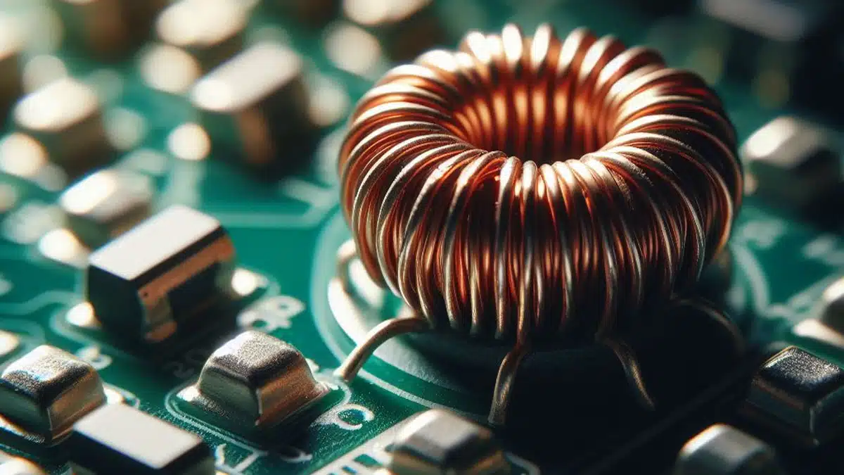
Depending on the topology, the primary inductance (L, or Lp) is the first important spec needed to figure out.

For the Inductor, that would be the measured inductance across the terminals, while for the Transformer the primary inductance with the secondaries open. Measurements of inductance should be performed at least on the operating frequency range of the Magnetic part, as inductances vary with frequency!

For Transformers, the turns ratio n of the primary/secondary is also an indispensable parameter.

Depending on the topology and control options, both L and n need to be calculated. Without these specs, you can go no further. It’s common for uncertainty to surround these parameters, since the designer often needs to dive into equations to find a suitable range of values. Usually, the story is quite simple for Inductors, but not so much for Transformers!

Let’s pick some examples!

Figure 1 – A PSFB CT Converter

First example:

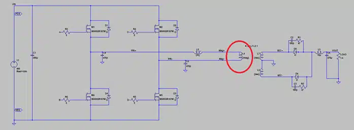
A client has a PSFB custom transformer and specifies 4mH of primary inductance. That much inductance is forcing the design into a high number of turns, thus increasing winding losses.

The question would be: Why does he need 4mH of inductance? Is he choosing to operate the PSFB Converter with peak current mode control scheme? The solution in this case is to double check the minimum inductance needed to safely operate in current mode control in this case and have a chat about it.

Second example: what should be the turns ratio in a PSFB?  

With the fair assumption that a maximum effective duty cycle of 70% is selected, given the highest/lowest voltages on the output/input respectively, we can calculate a turn ratio. Now, if the client does not have a clue of the effective duty cycle parameter, then we can ask for more info on his system to double check if this is the case.

Insulation

Do we need functional, basic, or reinforced isolation for the transformer design?

Don’t worry about the details. If that’s a new concept for you, we can propose appropriate insulation to meet certain standards for your product. The point with insulation is not only to pass the standards, but also to ensure the safety of the end-product user.

Cooling and Space

We are building a Magnetic part, let’s assume a Transformer. Typical efficiencies range vary from 98.4% to 99.7%. Although Magnetics are extremely efficient components by nature, there are losses that are then translated into heat, and we need to account for that.

Depending on the power level of the Converter, heat dissipation will result in a temperature rise. The usual specification is to keep temperature below a certain point under worst ambient temperature conditions. To achieve this, we need to cool the Magnetic somehow.

3 options for cooling are:

  • Natural convection cooled design.
  • Forced air cooling.
  • Potting and plate cooling

The Transformer temperature models we have developed will point us in the right direction once a design has been simulated and its power losses calculated. We need to keep in mind that the maximum dimensions of the Magnetic component will heavily influence the design options thus power losses, temperature rise and finally cooling method.

Samples and Production

When a salesperson inquiry about mass production volume and timelines, their intent is clear: ensure feasibility within specified timelines and cost structures that align with both the client’s and Frenetic’s objectives. No mysteries here…

But when our engineers ask you these very questions, why is that? The difference between creating a functional sample meeting specifications and designing a product suitable for large-scale manufacturing becomes apparent. That’s just reality. When we start with mass production as a goal with certain price tags, the designs are going to be different, even at the initial sampling stage.

Related

Source: Frenetic

Recent Posts

Würth Elektronik Expands Nanocrystalline Cable Cores for Broadband EMI Suppression

23.6.2026
9

Bourns Releases Automotive Gate Driver Transformer for Isolated Power

22.6.2026
20

Vishay Unveils 1.5 kV IHDV High Voltage Power Inductors for EV and Industrial Converters

19.6.2026
28

DMASS: European Components Distribution Returns To Growth In Q1 2026

16.6.2026
58

German Component Distribution Market Rebounds in Q1 2026 According to FBDi

16.6.2026
39

Sumida Introduces SMD Metal Inductors for High‑Current Automotive DC/DC Converters

15.6.2026
31

Knowles Expands High Q Ceramic Core Inductors

11.6.2026
38

Vishay Extends Automotive Ferrite Beads for High‑Current EMC Noise Filtering

10.6.2026
39

Modelithics Releases COMPLETE Library v26.2 for Keysight Genesys

8.6.2026
26

Upcoming Events

Jun 30
17:00 - 18:00 CEST

PSMA Capacitor Committee Webinar: High Voltage Pulse Capacitors

Jul 14
16:00 - 17:00 CEST

EMC Design Essentials: Mastering Varistors and Common Mode Chokes

Jul 21
16:00 - 17:00 CEST

Safety by design: X and Y Interference suppression capacitors for power line filters

View Calendar

Popular Posts

  • Boost Converter Design and Calculation

    0 shares
    Share 0 Tweet 0
  • Buck Converter Design and Calculation

    0 shares
    Share 0 Tweet 0
  • LLC Resonant Converter Design and Calculation

    0 shares
    Share 0 Tweet 0
  • Flyback Converter Design and Calculation

    0 shares
    Share 0 Tweet 0
  • MLCC and Ceramic Capacitors

    0 shares
    Share 0 Tweet 0
  • Earthing Systems and IEC Classification Explained

    0 shares
    Share 0 Tweet 0
  • Nvidia Vera Rubin: Why One AI Rack Needs So Many More MLCC Capacitors

    0 shares
    Share 0 Tweet 0
  • Dual Active Bridge (DAB) Topology

    0 shares
    Share 0 Tweet 0
  • SEPIC Converter Design and Calculation

    0 shares
    Share 0 Tweet 0
  • MLCC Case Sizes Standards Explained

    0 shares
    Share 0 Tweet 0

Newsletter Subscription


Passive Components Blog

© EPCI - Leading Passive Components Educational and Information Site

  • Home
  • Privacy Policy
  • EPCI Membership & Advertisement
  • About

No Result
View All Result
  • Home
  • Knowledge Blog
  • Dossiers
  • PCNS

© EPCI - Leading Passive Components Educational and Information Site

This website uses cookies. By continuing to use this website you are giving consent to cookies being used. Visit our Privacy and Cookie Policy.
Go to mobile version