


This article written by Dr. Chema Molina, Frenetic describes the practical process How to design an inductor that also serve as inductor selection guide.
This article focuses on the design of DC output inductors for switched‑mode power converters, using the energy method and a practical buck‑converter example. For high‑energy inductors see related: “How to Design High Energy Power Inductor”.
Key Takeaways
- This article teaches you how to design an inductor, focusing on DC output inductors for switched-mode power converters.
- It explains the classification of inductors and emphasizes collecting essential design data, such as inductance and current parameters.
- Core material selection, such as ferrite or powder, is crucial for achieving desired inductance and efficiency.
- The Energy Method helps calculate the energy needed for the design, ensuring the selected core can accommodate it.
- Finally, consider checking catalog options to find suitable off-the-shelf inductors to streamline the design process.
In the first place, we will classify the types of inductors.
Each type of inductor is specific for a different application and the design procedure will be different.
Reading the basics of inductor design, you have to choose a core (with a specific gap or distributed gap), and a winding (selecting the type of wire) to comply with some electrical specifications of inductance and current rating.
- Low-Frequency Inductors (< 10 kHz of the operating frequency of the power converter)
- Inductors for Differential Mode Suppression in EMI filters
- High-frequency Inductors
- →AC current Inductors (>50 kHz of switching frequency without DC bias current)
- →DC current Inductors (>50 kHz of switching frequency with a DC bias current)
- →PFC inductor (CrCm is similar to an AC inductor and CCM is similar to a DC inductor)
Therefore, the work consists of finding a combination of the core, gap, and winding to provide a specific inductance at a specific frequency and current ratio, avoiding saturation (magnetic materials can saturate, which means, the inductance effect disappears) and does not burn out.
Let’s start with the DC Current Inductor. Remember, to join the Online Webinar, you need to register here.
DC Current Inductor Design
This type of inductor is commonly used in DC/DC converters, where its function is critical. Some topologies are buck, boost, or buck-boost converters, Output inductors in Full Bridge where the converter functionality consists of chopping the input energy with the transistors, storing this energy in the inductor during a first interval, and delivering the energy to the load in the second interval.
The main difference between a DC inductor and others is the dominance of a DC current with respect to the AC current. The waveform of a buck converter keeps the B-H loop operating with a dB bias.
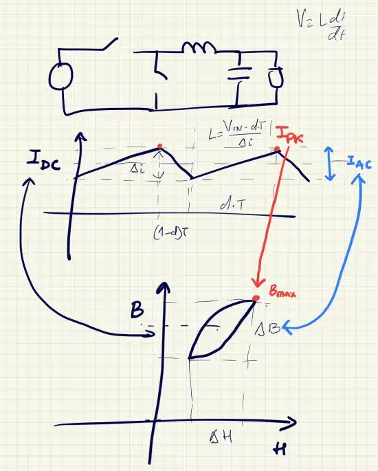
We can see the current ripple due to the Iac, which provokes the main core losses, and the Ipeak current, which affects the saturation limit.
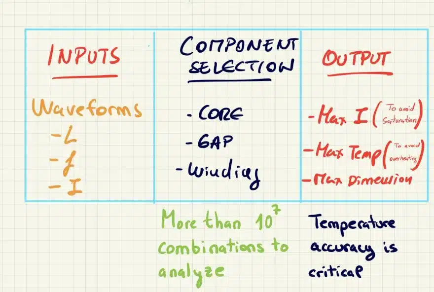
Collecting Data Before Starting the Design
The basic information needed to make the design is:
Converter waveforms to extract:
- Inductance
- IDC
- IAC
- IPEAK
- Fsw
These are the basic parameters, however, in industrial designs is common to have some standards or mechanical constraints, these are some examples:
- Industry Standard (Ex: Automotive, Space, Medical, or others)
- Temperature conditions. You can have ambient or maximum temperature due to the application
- Dimensions. Due to the mechanical design of the whole system is typical to have at least a dimension limit, it’s very common to have a footprint fixing 2 dimension limits.
- Overload current. It is typical to have inrush currents or transients where a certain overload current is flowing through the inductor. In those cases, the inductance should not drop and therefore the peak current should be considered to avoid saturation.
Starting the Design
Once we have all the information needed. we will start the design by selecting the core. There are several materials of cores, however, for this type of DC current (up to hundreds of Amperes) and frequency (up to several MHz), the most common is to use ferrite or powder depending on the variability of the inductance requirement. Other materials like nanocrystalline or amorphous will be discussed in future examples.
Core Materials for Power Inductors – Practical Overview
In practice, DC output inductors for switch‑mode converters are built mainly from ferrite and powder cores, with nanocrystalline and amorphous reserved for higher energy density or special EMI and temperature requirements. The brief comparison below helps narrow down the material family before you start detailed sizing and gap calculation.
| Core family | Typical use‑case window | Pros (for power inductors) | Cons / watch‑outs |
|---|---|---|---|
| MnZn ferrite | 50 kHz – 1–2 MHz, DC or DC+AC ripple | Low core loss in this band, good permeability stability vs frequency, many standard shapes | Saturation typically 300–360 mT, brittle ceramics, needs gapping for DC bias |
| Iron powder | 20 kHz – few 100 kHz, high DC bias | Distributed air‑gap (softer saturation), tolerant to large DC, good energy storage | Higher core loss than ferrite at high frequency, larger volume for same inductance |
| Sendust / FeSiAl | 20 kHz – 500 kHz, PFC chokes, DC chokes | Low loss at moderate frequency, good DC bias, low magnetostriction (low audible noise) | Limited shape/library vs ferrite, higher cost than basic iron powder |
| Nanocrystalline | 10 kHz – 500 kHz, high‑power, high‑density | Very high permeability, high saturation, excellent for compact high‑energy inductors | Costly, often tape‑wound toroids, careful handling of stray field and EMI |
| Amorphous | 10 kHz – 500 kHz, line chokes, high‑energy | Good loss performance, high saturation, robust against DC bias for certain grades | Similar constraints as nanocrystalline, fewer standard catalog parts |
When the design target is a compact, high‑frequency output inductor (for example 50–500 kHz buck), a gapped ferrite E/PQ/EQ core is usually the first choice. For lower switching frequencies with large DC bias (PFC boost choke, automotive 48 V converters) an iron powder or sendust core may offer better inductance stability and lower audible noise at the cost of some extra volume.
Core Material Selection
There are a lot of options inside ferrite materials. Ferrite Materials use to be characterized by their
- Permeability
- Frequency operating range
- Temperature operating range
- The magnetic field saturation limit
The classic materials used for DC inductors are selected to have a constant permeability. Typical materials in the range of 50 kHz to 1-2 MHz are shown in the following Figure 3.
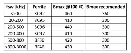
Within the ferrite materials, you can find normal saturation materials, which I recommend keeping the saturation under 300 mT, or high saturation materials, where you can go up to 360 mT. In any case, you can check each core shape datasheet to get the specific value.
However, selecting the material without a specific shape doesn´t make sense. Therefore, we need to analyze the combination of material, shape, gap, and number of turns.
Design Methods
There are more than 5 billion combinations of cores, windings, and turns, therefore, engineers have created some methods to reduce the options to be analyzed.
Experience designers use their past experiences with specific core families and materials to select the combinations to be analyzed.
However, I want to explain some methods which can help you in choosing the right core.
Area Product Method
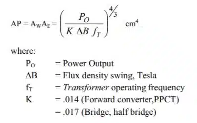
One of the most common methods is the Area Product method, which consists of calculating a value using the energy stored (current and inductance), frequency, maximum magnetic field (determined by the material used), and current density through the winding.
Each core shape (independent of the material) has assigned an Ap value, therefore, you can calculate your Ap, choose a specific core with a greater Ap value and be sure, the material you are going to use have the saturation limit you established at the beginning.
The value considers the space of the window to the windings, assuming some imperfections. This effect is represented by the k Factor, which is particular for each type of converter.
This is a perfectly valid method, but in my humble opinion, this method is more appropriate to design transformers because the gap it’s not considered.
Losses Method
I learned this method in the Unitrode books. There is an article called “Design Review: 500Watt, 40W/in3 Phase Shifted ZVT Power Converter” by Bill Andreycak which explains this method.
Since you know the maximum losses of your converter for a target efficiency, you can estimate the losses in the magnetic and select the components which have these losses.
We have launched recently a new product, which enhances this method to optimize the core selection.
Once you choose the losses of the core and winding, you can calculate the losses of your core candidates for a different number of turns.
The advantage of this method is the confidence in the maximum temperature rise since you can start the design from there.
The main drawback is the accuracy of your model to convert losses in temperature and the number of manual calculations you need to run to find the optimal core. I recommend this method for transformer designs
The Energy Method
And for me, the most appropriate method for inductors is the energy method. This method consists of calculating the energy needed for your design.
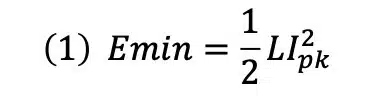
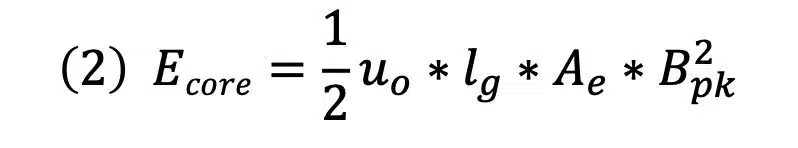
Understand the energy stored by your inductor and ensure that the volume of the gap is large enough to store that energy (1). And you can calculate the energy stored in the cores which are candidates for different gap values with (2).
The energy calculated for each core and gap should be greater than the energy needed.
If Ecore > Emin this core is a valid candidate.
Let’s do an example.
Design Example of a DC inductor using Energy Method
The following design will be based on the following specifications of a Buck converter.


We will run simulations (or use equations) to find the information needed for the design. In my case, I will run a simple simulation to get the values of the table below.
Core selection
With this data, I will choose the core using the energy needed. Based on (1) we have:
(3) E =1.66 mJ
I will calculate the energy storing capacity for some cores, using standard material for this frequency, 3C92. I have chosen the PQ and EQ cores because all of them fit in the dimensions. To do a professional design, the gap should be in the center leg and to avoid problems in the manufacturing stage, the minimum gap is 0,1 mm and the minimum step is 0,01 mm. I have chosen a range from 0,25mm to 1mm.
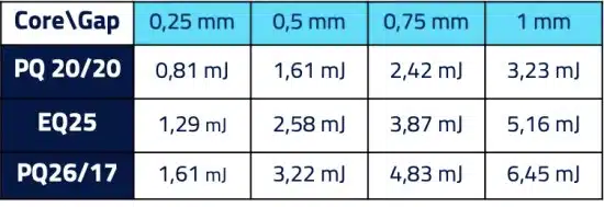
As you can see here, the valid cores will be the combinations of core and gap with greater values than 1,6 mJ. As we can see, all the cores have some valid options.
However, I will follow this rule to choose the optimal option.
As smaller the gap, less turns I will need for the same inductance. With lower losses, lower DC losses dominate here (I assume core losses to be very small).
- None of the cores are valid for gap =0,25 mm.
- EQ25 and PQ26 are valid for gap=0,5 mm.
- I have chosen the EQ25 because it’s smaller.
Turns calculation
With the core and gap selected and the desired inductance, we can calculate the number of turns needed. The value of the gap could vary to have a specific value of inductance.

For the EQ25, the number of turns needed is 9,6 to get the 22 uH. I chose an integer value, 9 turns, and adjust the gap to get the 22 uH. In these equations, we are not considering the fringing fields which affect to the inductance value. We will talk about this effect in the Online Webinar we will have on the 1st of December.
Practical Notes on Fringing Flux and AC Loss
In gapped cores, the magnetic field “bulges” out around the gap region, so part of the flux travels in air and in the copper instead of staying inside the ferrite.
This fringing flux slightly reduces the effective inductance vs the ideal equations and increases local copper loss and hot‑spots near the gap if conductors are too close.
From a practical design point of view, it is good practice to keep a minimum distance between the gap and the first turn and to avoid placing wide copper foils directly across the gap region. Many designers also distribute the total gap into several smaller gaps if the core family allows it, which reduces local fringing intensity and makes the inductance less sensitive to manufacturing tolerances.
In this introductory example, fringing and frequency‑dependent are neglected; in real designs you should always verify that the final geometry still meets inductance tolerance and temperature‑rise limits after including these effects in simulation or measurement.
Winding selection
To choose the wire technology, you can use simple rules
DC dominant current
Foil, rectangular wire, or round wire with one or 2 layers maximum (You sacrifice Rac losses versus DC losses)
Intermediate cases
If you can keep one layer, rectangular and round could work but to reduce the skin effect Litz wire could be the best option
AC ripple is dominant or very high frequency
Litz wire to reduce Rac.
In this case, we are talking about a dominant DC current, therefore, the rectangular wire will be preferred.
Once you’ve settled on a winding technology, it’s worth mapping that choice onto the inductor construction types you’ll actually find in catalogs or specify to a custom house:
| Inductor / core type | Typical converter use | Key advantages | Design / reliability concerns |
|---|---|---|---|
| Molded shielded power inductors | POL bucks, VRMs, compact DC/DC modules | Compact; good EMI due to closed flux; automated assembly | Core loss and percolation-type degradation at high voltage/temperature; limited saturation margin |
| Wire-wound on ferrite core | Higher power bucks/boosts, PFC chokes | Good efficiency; wide range of inductance and current ratings | Leakage fields and EMI; mechanical size; audible noise in some designs |
| Flat-wire inductors | High current, high density converters | Reduced copper loss; good thermal paths; lower AC resistance | Manufacturing complexity; cost; careful layout integration needed |
Source: Passive Components for Power Converters Dossier, Passive Components Blog (Table 5, Inductor Types, Converter Uses and Reliability Considerations). See related: Power Converter Dossier.
The number of turns and the gap is correlated, therefore, we need to see the best combination of losses.
First, we are going to choose a wire size. Check the bobbin window area and check the height, because the main goal is to have as minimum layers as possible (ideally one). In our case, we are going to use a rectangular wire and therefore we do not need to use a bobbin. To calculate the wire dimensions, we need to know what is the available height in the core and what is the minimum distance between turns that we have. In this case, we are going to take a 0.25 mm distance between turns and from the wire to the core.
Rectangular height= (Core_window_min_height – (Nturns-1) * distance_turn_to_turn – distance_between_turn_core)/Nturns = 10-(9-1)*0.25-0.5)/9 = 0.83
The value 0,83 mm is the available height for each turn. We need to consider the wire insulation which could be 0.1 mm or 0.2 mm depending on the grade of the wire. In this case, we have a Grade 1 rectangular wire and we can consider 0.7 mm of conducting height.
The minimum core width space is 5,2 mm, taking 0,5 mm of tolerance in each side, we ended up having a width wire of 4,2 mm, considering the isolation, we will have 4 mm of real width of conduction.
With this value, we can calculate the current density and DC losses:
Current density = 3, 2 A/mm2 ( For DC inductor, keep this value below 5A/mm2 with natural convection)
- Pdc= 0,26 W
- Pcore=0,09W
The total losses will be 0,35 W. As the design use only one layer, the proximity losses will be negligible for this design, and for DC dominant currents, the skin effect is also negligible.
For context, the 3.2 A/mm² used in this example sits well within the conventional natural-convection guideline. At the leading edge, AI server power stages using vertical power delivery are already pushing current density past 2 A/mm² in millimeter-scale modules with active cooling and very short power paths — a reminder that the “below 5 A/mm²” rule of thumb above assumes natural convection and a fairly conventional layout, and tightens or loosens depending on your actual thermal environment.
Source: AI Hardware Passive Components Dossier, Passive Components Blog (Section 2.2, Vertical Power Delivery). See related: AI Hardware Dossier.
Catalog Designs
The previous process allows us to design a custom piece, however, customizing a component is very expensive, therefore, I always recommend checking the availability of components from catalogs that fit in your design.
If we take the specifications of Table I and check in the libraries of manufacturers, we find the following design which fits perfectly in the converter.
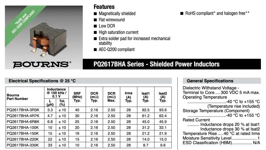
You can check in classic distributors filtering by inductance and rated current or visit Bourns page to look for the best option. In my case, I have used the finder of components at Frenetic Online, which recommends options of the best industry manufacturers and allows you to run simulations for this component.
Second article of Dr.Molina’s magnetics basics continue with his case study here: How to Design High Energy Power Inductor
Disclaimer
We haven´t included Rac and Fringing flux losses and impact on the inductance here, because this is a basic description of how to design an inductor. In our tool, Frenetic, we calculate the losses using complex models, some of which are based on laboratory measurements.
In the inductor example, we have considered the wire insulation to be enough for ensuring the insulation of the component. However, this topic could be discussed in our Online Event.
Quick Design Check – DC Output Inductor
Before freezing the design, verify at least:
- Electrical: Inductance at min/max current is within tolerance and avoids saturation under IPEAK and overload conditions.
- Thermal: Total losses (Pdc + Pcore) keep current density and temperature rise within your application and standard limits.
- Mechanical: Core size, window utilization, and minimum distances between turns and core/gap are manufacturable and respect creepage/clearance requirements.
- Standards: Any relevant automotive, industrial, or medical requirements for isolation, test voltages, and derating are reflected in your margins.
- Availability: A catalog inductor with similar performance is not a better cost/lead‑time compromise than a full custom part.
A concise, on‑brand summary/conclusion that fits your edited article could look like this:
Summary
Designing a DC output inductor starts with understanding the application waveforms and extracting key parameters such as inductance, IDC, IAC, IPEAK and switching frequency, together with thermal, mechanical and standards constraints.By selecting an appropriate core material and shape, applying the energy method to size the gap and turns, and choosing a suitable winding technology, you can achieve a design that meets inductance, saturation and temperature‑rise limits.
Once a custom design is validated electrically, thermally and mechanically, it should be compared against available catalog inductors to check whether an off‑the‑shelf solution offers a better trade‑off in cost and lead‑time. This article provides a practical reference for junior and practicing power‑electronics engineers who need a structured, repeatable approach to DC output inductor design using the energy method.
FAQ
Inductors can be classified into low-frequency inductors (<10 kHz), EMI suppression inductors, high-frequency AC inductors (>50 kHz without DC bias), high-frequency DC inductors (>50 kHz with DC bias), and PFC inductors. Each type is optimized for different applications and design requirements.
You need converter waveforms and parameters such as inductance, IDC, IAC, IPEAK, and switching frequency (Fsw). Additionally, consider industry standards, temperature limits, mechanical dimensions, and overload current conditions.
Ferrite and powder cores are most common, depending on inductance variability. Ferrite materials are characterized by permeability, frequency range, temperature range, and saturation limits. High-saturation ferrites can reach up to 360 mT.
Three common methods are: (1) Area Product Method, (2) Losses Method, and (3) Energy Method. The Energy Method is often preferred for inductors, as it ensures the gap volume can store the required energy.
Winding choice depends on current type: foil or rectangular wire for DC-dominant currents, Litz wire for high-frequency AC ripple, and round wire for intermediate cases. The goal is to minimize layers, reduce losses, and ensure proper insulation.
How to Design a DC Current Inductor
- Collect Design Data
Gather converter waveforms and parameters: inductance, IDC, IAC, IPEAK, and switching frequency. Include constraints such as temperature, dimensions, and overload current.
- Select Core Material
Choose ferrite or powder cores based on frequency and current requirements. Verify permeability, operating range, and saturation limits. Match material with core shape and gap.
- Apply a Design Method
Use the Energy Method to calculate required energy storage. Ensure the selected core and gap combination can store more energy than the design requires.
- Calculate Turns
Determine the number of turns needed to achieve the target inductance. Adjust the gap size to fine-tune inductance while minimizing losses.
- Choose Winding Type
Select wire technology based on current profile. For DC-dominant designs, rectangular wire is preferred. Ensure minimal layers and proper insulation clearance.
- Validate Losses
Calculate DC and core losses. Keep current density below 5 A/mm² for natural convection. Ensure total losses remain within thermal limits.
- Check Catalog Options
Compare custom design results with catalog components from major manufacturers. This can reduce cost and speed up development.


