In this video prof. Sam Ben-Yaakov explains basic operation principles of variable inductor.
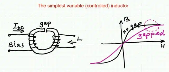
A variable inductor can tune inductance by applying DC bias to a control winding, allowing a magnetic component to adapt the resonant behaviour of a power converter. The presented magnetic-bypass arrangement is intended to retain the useful inductance-control effect while keeping the AC current induced in the DC-bias winding low, particularly when the magnetic material operates at high permeability.
Key Takeaways
- The video explains the operation principles of a variable inductor, which adapts inductance by applying DC bias to a control winding.
- Variable inductors help maintain target operating points in resonant and switched-mode converters despite changes in input voltage or load.
- The proposed magnetic-bypass arrangement minimizes AC current in the DC-bias winding, reducing losses and thermal stress.
- Designers should consider leakage inductance and use a model that reflects actual measurements for accurate performance prediction.
- The variable inductor was successfully tested in a 600 W LLC converter, adjusting inductance to maintain a fixed switching frequency.
Why this topic matters
Many resonant and switched-mode converters require an inductance that changes with operating conditions. A controllable inductor can therefore be used to compensate for changes in input voltage or load while maintaining a target operating point, such as a fixed switching frequency.
The main practical concern is the control winding. If appreciable AC flux links that winding, it produces an AC voltage and circulating AC current. That additional current increases RMS winding current and can add copper loss, thermal stress and control-circuit burden.
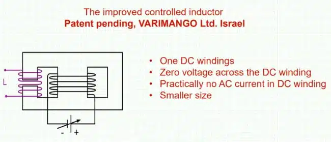
The video presents a magnetic-bypass structure in which the AC-winding flux is preferentially routed through an alternative magnetic path. The DC control flux changes the reluctance of a central leg and thereby changes the inductance seen by the main winding.
Operating principle
The proposed magnetic element has three magnetic legs:
- A central leg carrying the DC-bias winding
- A left leg carrying the main AC inductor winding
- A right leg that provides the magnetic bypass path
The AC winding generates magnetomotive force and corresponding AC flux. That flux can return through either the central leg or the bypass leg. In the high-permeability, low-bias condition, the magnetic-bypass arrangement is intended to direct most AC flux through the bypass path rather than the DC-control leg.
This substantially reduces the AC flux linking the DC winding. Because the induced voltage depends on changing flux linkage, a smaller AC flux component in the central leg leads to a lower induced AC voltage and, consequently, lower circulating AC current in the DC-bias circuit.
The central-leg DC flux changes magnetic reluctance as the bias current changes. As the effective permeability falls under increasing DC bias, the inductance measured at the AC winding is reduced. This is the same broad behaviour that underlies inductance reduction under DC bias and magnetic saturation.
Reluctance-equivalent model
A conventional magnetic-reluctance equivalent circuit represents the winding excitation as a magnetomotive-force source. The presentation introduces an alternative representation in which the winding-related element is replaced by an inductor:
where N is the number of turns and Rs is the electrical resistance associated with the winding in the model.
The video explains that a low winding resistance and a relatively high turn count result in a large equivalent inductance. At switching frequency, the impedance of that inductive branch becomes high. The reluctance-network model therefore predicts that only a small portion of AC flux enters the central DC-bias leg when the magnetic material is at high permeability.
This is a modelling approach rather than a replacement for electromagnetic verification. Designers should compare the model with measured inductance-versus-bias behaviour, parasitic inductance, winding resistance and operating waveforms.
Flux distribution and AC current
At zero DC bias, the simulation presented in the video shows approximately equal AC flux in the left, AC-winding leg and the right bypass leg: about 1.8 micro-weber in each path. The AC flux in the central DC-bias leg is reported to be approximately one order of magnitude lower.
Under this zero-bias condition, the simulated AC current in the DC winding is approximately 2 mA. The low value is attributed to the low AC-flux linkage of the central leg.
With a sufficiently high DC-bias current, the effective permeability falls and the AC-flux distribution changes. The video reports approximately 3.6 micro-weber peak-to-peak AC flux in the AC-winding leg and approximately 3.5 micro-weber in the bypass leg. Their difference—corresponding to flux entering the central path—is reported as approximately 4 nano-weber.
The simulated AC current in the DC winding then increases to approximately 78 mA RMS. However, the video notes that this is small compared with the approximately 3 A DC-bias current, so its contribution to total RMS winding current and winding loss is limited in the illustrated case.
| Operating condition shown | AC flux behaviour | DC-winding AC-current result |
|---|---|---|
| Zero DC bias | Central-leg AC flux substantially lower than flux in the main and bypass legs | Approximately 2 mA |
| High DC bias | Reduced permeability changes flux sharing; more AC flux reaches the central leg | Approximately 78 mA RMS |
| Approximately 3 A DC bias | DC component dominates total RMS current in the illustrated case | Additional AC-loss penalty described as limited |
The numerical values above are simulation examples from the presentation, not general component specifications. Actual behaviour depends on core geometry, material characteristics, air gaps, winding placement, conductor resistance, current waveform and frequency.
Inductance control range
The simulated inductance-versus-bias result in the video falls from approximately 40 microhenry at zero bias to approximately 6 microhenry at 3 A. The presenter notes that this simulation did not include leakage inductance, which affects the attainable minimum inductance.
Measured behaviour showed a smaller tuning range, falling from approximately 40 microhenry to approximately 16 microhenry or slightly below. This difference highlights an important design principle: magnetic-component modelling should include leakage and other parasitic elements when the required minimum inductance is important.
LLC converter demonstration
The experimental demonstration used the variable inductor in place of the fixed series resonant inductor of a 600 W LLC converter demonstration board. The converter was operated in closed loop, and the variable inductor was adjusted to maintain a switching frequency of 100 kHz.
The tests covered input voltages of 350 V, 380 V and 410 V, with load varied up to approximately 600 W. The original design used a fixed series inductance of approximately 16 microhenry.
At 350 V input, the original approximately 16 microhenry inductor was reported to maintain an operating frequency of about 100 kHz. At higher input voltages, the original fixed-inductor arrangement would shift frequency, whereas the demonstrated setup adjusted the variable series resonant inductance to restore operation at 100 kHz.
An LLC converter uses a resonant tank consisting of resonant inductance, resonant capacitance and transformer magnetising inductance. Changing the series resonant inductance changes the tank impedance and resonant behaviour; therefore, the variable-inductor setting must be evaluated together with switching frequency, voltage gain, soft-switching margin, circulating current and thermal performance. See also LLC Resonant Converter Design and Calculation.
Design-in notes for engineers
- Confirm whether the required inductance is a small-signal value, a differential inductance under DC bias, or an effective value under the actual AC current waveform.
- Characterise the complete inductance-versus-DC-bias curve across the expected temperature range; do not base converter control solely on the zero-bias inductance.
- Measure AC current in the DC-bias winding at minimum and maximum bias. Low AC current at zero bias does not guarantee equally low current once DC bias has reduced permeability.
- Include leakage inductance in the model and measurement plan, particularly when the intended design relies on a low minimum inductance.
- Calculate copper loss using total RMS current, including DC and AC components, and account for temperature-dependent winding resistance.
- Check high-frequency winding effects, including skin effect and proximity effect. A low DC resistance alone does not ensure low switching-frequency loss; see Inductance, Impedance, Q Factor and DCR Losses.
- Validate core loss under the actual flux-density swing and switching frequency, including the influence of DC bias on material behaviour.
- Evaluate the full LLC operating envelope, including input-voltage range, load range, resonant-current stress, zero-voltage-switching margin and control-loop response.
- Verify thermal margin experimentally using the final core, winding, insulation system, DC-bias supply and mechanical assembly.
- Assess conducted and radiated EMI after integrating the controllable magnetic element, since altered resonant conditions and current waveforms can change the converter noise spectrum.
Limits and trade-offs
The magnetic bypass does not eliminate AC coupling into the DC-bias winding under all operating conditions. The presentation shows that AC current in this winding rises as the DC bias reduces effective permeability and changes flux distribution.
Leakage inductance also constrains the usable control range. It can prevent the inductor from reaching the low inductance predicted by a simplified reluctance model, as demonstrated by the difference between the simulated minimum of approximately 6 microhenry and the measured minimum near 16 microhenry.
A variable inductor adds magnetic structure, a control winding and a DC-bias supply to the converter. Its value must therefore be judged against alternative approaches such as switching-frequency control, selectable inductors or other resonant-tank design changes. The suitable approach depends on the required control range, efficiency, cost, reliability and allowable complexity.
Conclusion
The magnetic-bypass variable inductor provides a practical way to adjust inductance with DC bias while reducing AC-flux coupling into the control winding in the high-permeability condition. The LLC-converter demonstration shows that this controllable series inductance can compensate for operating changes and maintain a 100 kHz switching frequency across the illustrated input-voltage and load range.
Its practical control range is limited by permeability reduction, AC current in the bias winding and parasitic leakage inductance. Engineers should therefore validate inductance-versus-bias characteristics, total RMS winding loss, temperature rise, resonant-tank behaviour and soft-switching margin in the completed converter rather than relying solely on a simplified reluctance model.
FAQ – Variable Inductors
A variable inductor is a magnetic component whose inductance can be adjusted during operation. In the presented arrangement, DC current in a control winding changes the magnetic reluctance of the core and therefore changes the inductance seen by the main AC winding.
Increasing DC-bias current reduces the effective permeability of the magnetic path. This increases reluctance and lowers the inductance measured at the AC winding; in the illustrated measurement, inductance changed from about 40 microhenry at low bias to about 16 microhenry or slightly lower at higher bias.
The bypass provides an alternative path for AC magnetic flux produced by the main winding. At low DC bias and high permeability, it reduces the portion of AC flux entering the central leg with the DC-control winding, helping to limit induced AC voltage and circulating AC current in that winding.
High DC bias reduces magnetic permeability and changes how AC flux divides between the bypass path and the central control leg. More AC flux can then link the DC winding, increasing its induced AC voltage and circulating AC current.
Leakage inductance and other magnetic parasitics can set a practical lower limit. In the presented example, simulation predicted an inductance near 6 microhenry at 3 A bias, whereas the measured inductor reached approximately 16 microhenry or slightly below.
The variable inductor replaced the fixed series resonant inductor in a 600 W LLC converter demonstration board. Its inductance was adjusted in closed-loop operation to maintain a 100 kHz switching frequency across the demonstrated input-voltage and load conditions.
Further reading
- What Is an Inductor?
- Modified Magnetic Reluctance Equivalent Circuit and its Implications
- Variable Controlled Inductor in LLC Converter Application Example
- Designing a 2 kW LLC Transformer with Integrated Resonant Inductor
References
This article adapts the technical presentation by Professor Sam Ben-Yaakov. The values and experimental observations described above are those presented in the video and should be validated for each specific magnetic design and converter operating condition.