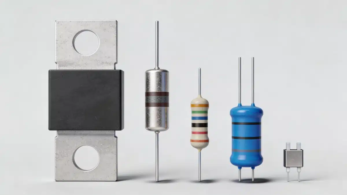
This guide compares resistor technologies that sit outside the mainstream thick-film chip and conventional thin-film resistor families: metal-element, metal-oxide film, metal-glaze/cermet, carbon-film, carbon-composition, conductive-plastic, and bulk-metal-foil resistors. It explains how their construction affects resistance range, continuous power, working voltage, pulse capability, stability, temperature coefficient, excess noise, parasitic behaviour, and practical applications.
The technology name is only a starting point. Final component selection must be based on the data sheet for the exact resistor series, package, mounting method, ambient temperature, voltage stress, pulse waveform, repetition rate, and required lifetime accuracy.
Key takeaways
- Metal-element resistors are the primary choice for milliohm current sensing, high-current paths, and power dissipation where low resistance and robust thermal behaviour are required.
- Metal-oxide and metal-glaze resistors are widely used in high-voltage, surge, and mains-connected applications, but short-pulse capability must always be verified from the series-specific pulse-load curve.
- Carbon-film resistors remain useful in cost-sensitive and selected high-resistance applications, although their noise, drift, and temperature coefficient are generally less favourable than modern metal-film technologies.
- Carbon-composition resistors are mainly relevant to restoration, legacy qualification, and narrowly defined pulse applications; they are rarely the preferred option for a new design.
- Conductive plastic is principally a resistive-track technology for potentiometers and position sensors, not a general-purpose fixed-resistor technology.
- Bulk-metal-foil resistors are intended for precision analogue, metrology, and stable reference applications where exceptionally low TCR, low excess noise, and long-term stability justify their cost.
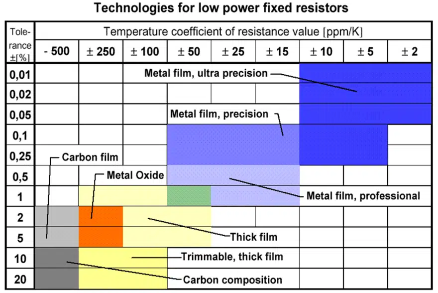
The following Table 1. compares TCR vs tolerance for resistor technologies comparing its key characteristics
How to compare resistor technologies
Resistance value, tolerance, and nominal power rating are not enough to select a resistor reliably. A resistor may survive its rated continuous dissipation but fail under a short pulse, exceed its working-voltage limit, introduce unacceptable sensing error, or drift beyond the circuit error budget.
| Parameter | Why it matters | Typical design question |
|---|---|---|
| Continuous power and derating | Rated power applies only under stated ambient and mounting conditions. The allowable dissipation falls as body or ambient temperature rises. | What is the hottest local ambient temperature, and what power remains after derating? |
| Working voltage and overload voltage | High resistance does not automatically mean high voltage capability. Element voltage gradient, creepage, PCB clearance, and surface contamination can become limiting factors. | Is the resistor’s continuous working voltage adequate, including mains tolerance and fault conditions? |
| Pulse energy and repetition rate | Single-pulse, repetitive-pulse, overload, and surge ratings use different test conditions and cannot be interchanged. | Does the exact series pass the required waveform, duration, energy, and number-of-pulses curve? |
| TCR, PCR, VCR, and drift | Ambient-temperature change, self-heating, applied voltage, and ageing can each change resistance. | Which resistance-change mechanism dominates the total error budget? |
| Excess noise and thermoelectric EMF | These effects can dominate low-level DC and precision analogue measurements even when nominal resistance tolerance is tight. | Is the resistor used near an ADC, reference, bridge, or microvolt-level sense signal? |
| Inductance, capacitance, and layout | Package geometry and PCB routing determine the high-frequency impedance and switching transient response. | Is the application a fast switching, RF, high di/dt, or high dv/dt circuit? |
| Safety and qualification | Flameproof, fusible, anti-surge, automotive, humidity, sulfur, vibration, and high-reliability requirements are series-specific. | Which applicable standard, end-equipment requirement, or environmental test must the component meet? |
Design rule: first define the electrical and thermal stress, then shortlist technologies, and finally qualify an exact resistor series using its derating, overload, pulse, voltage, and reliability data. For a practical method, see the resistor pulse-load and derating design guide.
Metal Element Resistors
Metal-Element Resistors
Construction and variants
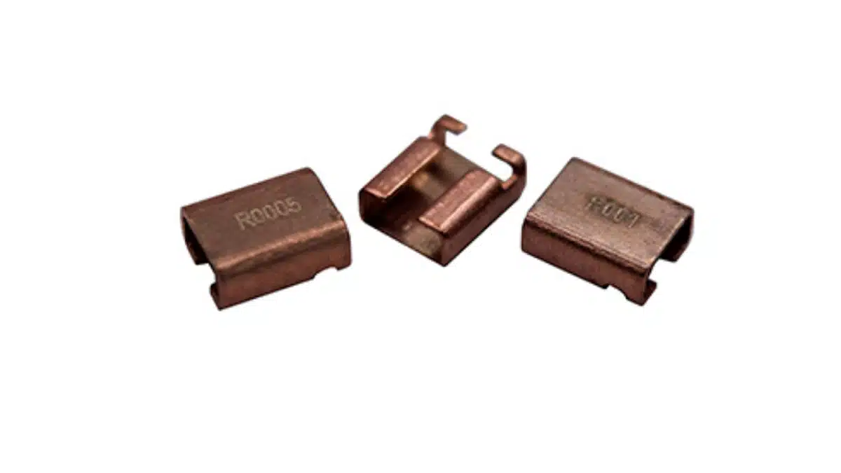
Metal-element resistors use a bulk-metal or metal-alloy conductor rather than a deposited resistive film. Their element is commonly a precision alloy strip, plate, stamped lead-frame feature, or etched pattern joined to copper terminals and protected by moulding, coating, or a ceramic-supported power-resistor structure.
- Flat alloy strips welded to copper terminals are common in low-ohmic current-sense resistors.
- Stamped or etched alloy patterns provide compact SMD shunts with controlled resistance and thermal performance.
- Ceramic-supported or chassis-mount constructions extend the technology to higher continuous power levels.
- Four-terminal versions separate the high-current path from the voltage-sense connection and reduce errors from leads, solder joints, and PCB copper.
Electrical characteristics
- Resistance range: typically from sub-milliohm values to a few ohms, depending on construction and power class.
- Power capability: ranges from fractional-watt SMD shunts to high-power chassis-mounted components. Package thermal resistance, copper area, airflow, and mounting method often limit usable power before the alloy element itself does.
- TCR and stability: depend on alloy, resistance value, geometry, and target application. Precision current-sense types use controlled alloys and constructions to minimise resistance change over temperature and time.
- Thermoelectric EMF: becomes important in milliohm and microvolt-level DC measurements because junctions between unlike metals can generate temperature-dependent offsets.
- Frequency behaviour: inductance is not an intrinsic property of all metal-element resistors. It depends on the current path, terminal geometry, package, and PCB layout. Low-inductance and reverse-geometry constructions are available, but their suitability must be confirmed from data-sheet impedance or inductance information.
Applications and design notes
Metal-element resistors are widely used for current sensing in DC/DC converters, motor drives, battery-management systems, automotive 12 V and 48 V systems, EV traction and charging equipment, industrial power supplies, and high-current protection circuits. In SiC- and GaN-based converters, the relevant limits may include bandwidth, package inductance, short-pulse capability, common-mode transient environment, and layout—not only resistance tolerance.
For low-value current sensing, use Kelvin connections wherever possible. Route the voltage-sense traces from the inner sides of the resistor pads or dedicated sense terminals, keep them away from switching-current loops, and avoid sharing copper or vias with the load current path. See the current-sense shunt resistor design guide for practical layout and error-budget guidance.
Advantages
- Very low resistance with high current capability.
- Good thermal robustness and useful overload performance in many power-oriented series.
- Low excess noise compared with granular carbon-based resistor systems.
- Available in two-terminal, Kelvin, SMD, through-hole, and chassis-mount formats.
Limitations
- Not usually suitable for high-ohmic signal functions.
- Short-pulse capability, inductance, TCR, and overload behaviour vary substantially between packages and series.
- Thermal gradients, solder-joint resistance, copper resistance, and thermoelectric offsets can dominate total measurement error at milliohm values.
Metal Oxide (METOX) and Metal Glaze Resistors
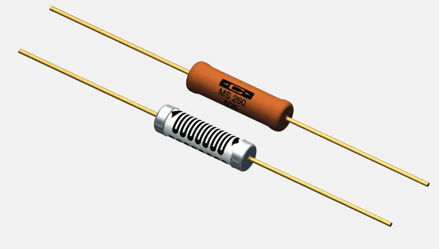
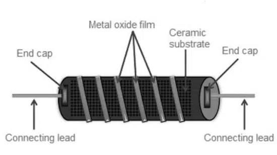
Metal-oxide film and metal-glaze resistors are both inorganic resistor systems, but they should not be treated as identical technologies. Metal-oxide film resistors use an oxide-based film on an insulating ceramic body, whereas metal-glaze or cermet constructions use conductive particles dispersed in a glass matrix and fired onto a ceramic substrate.
Construction
- Metal-oxide film: a ceramic rod or tube carries an oxide-based resistive film, commonly followed by a helical or serpentine trim to set the final value.
- Metal glaze / cermet: conductive metal or metal-oxide particles are dispersed in glass, screen-printed or otherwise deposited on a ceramic substrate, and fired to form a stable resistive layer.
- Terminations, protective coatings, creepage distance, and body geometry strongly influence working voltage, surge performance, and environmental robustness.
Electrical characteristics
- Resistance range: broad, from low-ohmic power parts to specialised high-resistance and high-voltage components.
- TCR and stability: typically moderate and strongly series dependent. They are usually less suitable than high-quality metal-film or bulk-metal-foil resistors when low drift and tight analogue accuracy are the main requirement.
- Noise: generally lower than carbon-based film and composition systems, but the exact excess-noise performance must be verified for precision circuits.
- Voltage performance: many families are designed for high working voltage, high overload voltage, or mains surge duty. The allowable voltage is limited by resistor body design, voltage gradient along the element, terminals, PCB creepage and clearance, and environmental contamination.
Pulse and environmental behaviour
Metal-oxide and metal-glaze resistors are often selected for robust overload and surge performance, especially in mains-connected and high-voltage circuits. However, a good long-duration overload rating does not automatically guarantee survival of a very short, high-amplitude pulse. Always evaluate the manufacturer’s pulse waveform, pulse duration, repetition rate, voltage, energy, and permitted resistance-change criteria for the exact resistor series.
Typical applications
- High-voltage divider chains, bleeders, and discharge resistors.
- Mains-connected droppers, start-up resistors, snubbers, and damping networks.
- Industrial, medical, X-ray, and power-conversion equipment where voltage withstand and environmental durability are important.
- Replacement designs for legacy carbon-composition parts where improved stability, flame resistance, or controlled surge performance is required.
Design caution
For high-voltage divider chains, calculate voltage stress per component, include tolerance and drift in the divider ratio, and consider PCB surface leakage, humidity, contamination, guard structures, conformal coating, and creepage/clearance. Do not infer high-voltage suitability solely from a high nominal resistance value.
| Characteristic | Metal-oxide film | Metal glaze / cermet |
|---|---|---|
| Resistive system | Oxide-based resistive film deposited on an insulating ceramic body. | Conductive metal or metal-oxide particles dispersed in a glass matrix and fired onto a ceramic substrate. |
| Value adjustment | Usually laser, abrasive, or helical trimming of the deposited film. | Normally controlled by composition, printed geometry, firing conditions, and trimming where required. |
| Resistance range | Broad; commonly used from low-ohmic power values into high-resistance and high-voltage ranges. | Broad and strongly product-family dependent, from discrete resistors to specialist networks and high-voltage designs. |
| TCR and stability | Usually moderate; depends on film material, geometry, coating, and operating stress. | Moderate to good; dependent on cermet composition, firing process, substrate, and package. |
| Excess noise | Generally lower than carbon-based film and composition systems; verify for precision analogue use. | Typically suitable for many industrial and power functions; verify the exact series for low-noise precision circuits. |
| Working-voltage behaviour | Often well suited to high working voltage, overload voltage, and mains-connected applications. | Can offer strong voltage and environmental performance, depending on geometry, coating, terminals, and creepage distance. |
| Pulse and overload behaviour | Many series are designed for overload or surge duty, but short-pulse performance is series and waveform specific. | May be robust in pulse and high-energy applications, but the permitted pulse energy and repetition rate must be taken from the data sheet. |
| Parasitics | Helical trimming may introduce inductance; body geometry and terminals also add capacitance. | Parasitics depend on the resistive pattern, terminals, substrate, and package construction. |
| Typical applications | Bleeders, droppers, start-up resistors, snubbers, damping circuits, surge paths, and high-voltage divider chains. | High-voltage, industrial, medical, power-conversion, and specialised network applications. |
| Main selection caution | Do not equate a continuous-power or overload rating with qualification for a short, high-amplitude pulse. | Do not treat all metal-glaze/cermet products as equivalent to metal-oxide film parts; assess the exact product construction and ratings. |
Carbon Film Resistors
Construction
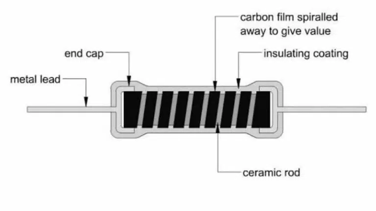
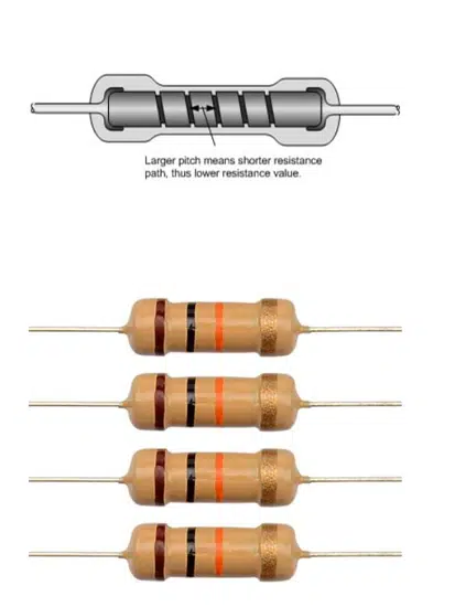
Carbon-film resistors use a carbon-based resistive film deposited on an insulating ceramic body. The film is usually trimmed by a helical cut to achieve the required resistance, then fitted with end caps or leads and protected by a coating. Film composition, thickness, trimming pattern, and coating determine the final electrical and environmental behaviour.
Characteristics
- Resistance range: broad, from low-ohmic values to high-resistance products, depending on the series.
- TCR: commonly negative and more variable than in precision metal-film resistor families.
- Stability: adequate for general-purpose designs but generally inferior to high-quality metal film and foil in long-term precision applications.
- Excess noise: typically higher than in metal-film, metal-oxide, and bulk-metal-foil technologies, particularly at higher resistance values.
- High-frequency behaviour: a helical trim can introduce inductance, while the body and terminals also introduce capacitance. Use impedance data rather than assuming a nominally resistive response at high frequency.
Pulse capability
Carbon-film pulse performance is strongly construction-specific. Some low-ohmic, thick-film, or non-spiral constructions can tolerate useful pulse energy because current is distributed over a larger effective film area. This must not be generalised to every spiral-trimmed carbon-film resistor. For any surge, discharge, ignition, crowbar, or protection application, use the pulse-load curve for the exact part series and test the intended waveform where the consequence of failure is significant.
Typical uses
- Cost-sensitive general-purpose circuits where wide tolerance and moderate drift are acceptable.
- Selected pulse, damping, and protection functions when the exact resistor series is specified for the required waveform.
- High-resistance applications using specialised sealed products, provided insulation resistance, board leakage, handling contamination, humidity, and voltage rating are controlled.
| Characteristic | Carbon-film resistor | Design implication |
|---|---|---|
| Resistive system | Carbon-based resistive film deposited on an insulating ceramic body and protected by an outer coating. | Film composition, thickness, coating, and manufacturing control determine the electrical and environmental performance. |
| Resistance adjustment | The deposited film is commonly trimmed with a helical cut to achieve the specified resistance value. | Helical trimming can increase parasitic inductance; check impedance or inductance data in high-frequency and fast-switching circuits. |
| Resistance range | Broad, from low-ohmic values to high-resistance products, depending on the resistor series and package. | Do not infer working-voltage capability solely from a high nominal resistance value. |
| TCR | Typically negative and usually more variable than in precision metal-film resistor families. | Evaluate the full operating-temperature range where gain, timing, threshold, or divider accuracy is important. |
| Long-term stability | Generally adequate for general-purpose electronics but less favourable than high-quality metal-film and bulk-metal-foil technologies for demanding precision applications. | Include expected ageing, humidity, temperature cycling, and operating-load effects in the resistance-error budget. |
| Excess noise | Normally higher than in metal-film, metal-oxide, and bulk-metal-foil resistor technologies, particularly at higher resistance values. | Use caution in low-level DC, high-gain analogue, reference, bridge, and audio circuits where excess noise can be significant. |
| Pulse and overload behaviour | Strongly construction- and series-dependent. Some specialised types can provide useful pulse capability. | Verify the exact manufacturer pulse-load curve, including waveform, duration, repetition rate, voltage, energy, and permitted resistance change. |
| Frequency behaviour | The trim pattern, body dimensions, leads, and terminals introduce non-ideal inductance and capacitance. | Use the manufacturer’s impedance data or validate the actual part in circuits with high di/dt, high dv/dt, RF, or fast switching edges. |
| Environmental sensitivity | Performance can be affected by moisture ingress, contamination, coating integrity, mechanical stress, and repeated thermal cycling. | Select a suitably sealed and qualified product family for demanding industrial, automotive, or humid-environment use. |
| Typical applications | General-purpose electronics, selected damping and protection functions, and specialised high-resistance applications. | Use only series-specific qualification for surge, discharge, ignition, crowbar, or safety-related applications. |
| Main selection caution | Carbon-film technology is not a universal low-cost substitute for metal film, pulse resistors, or high-voltage resistors. | Select by the required accuracy, noise, voltage, thermal, pulse, and reliability conditions—not by the carbon-film label alone. |
Carbon Composition Resistors
Construction
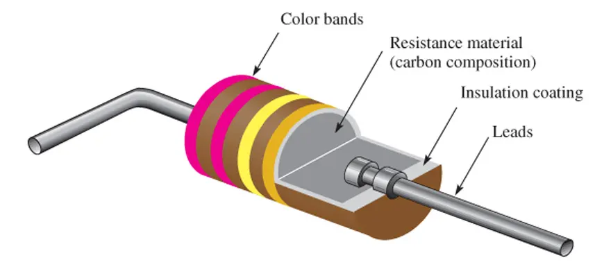
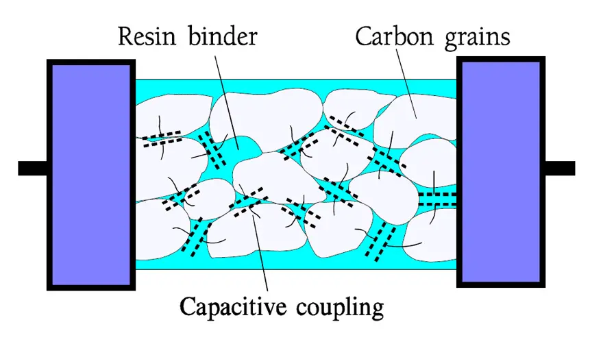
Carbon-composition resistors are bulk resistors made from carbon particles, insulating fillers, and a binder or resin moulded into a resistive body. Unlike a film resistor, current flows through a distributed granular network rather than through a thin deposited layer. Historical product quality and construction vary widely, so performance should not be inferred from the generic technology label alone.
Electrical and frequency behaviour
- Inductance: the distributed current paths can produce relatively low inductance compared with a conventional helical film or wirewound construction.
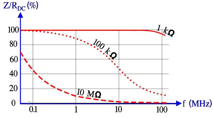
- Impedance: the granular structure also produces capacitance and non-ideal frequency behaviour, so low inductance does not mean a carbon-composition resistor is ideal at all frequencies.
- TCR and stability: resistance change can be strongly non-linear with temperature, humidity, applied voltage, and age.
- Noise: excess current noise is generally high because conduction occurs through a granular contact network.
Pulse behaviour
Low inductance alone is not a pulse rating. High surge current can stress or damage microscopic conductive contacts inside the composition, causing resistance change or failure. Some low-resistance, purpose-designed carbon-composition parts may be useful in specific pulse circuits, but pulse suitability must be demonstrated by the manufacturer’s test data or by application testing under the actual waveform and repetition rate.
Where:
- E is pulse energy in joules (J)
- P is pulse power in watts (W)
- t is pulse duration in seconds (s)
For a resistor with a rectangular pulse voltage V applied across resistance R, the equivalent forms are:
or, if current is known:
For a rectangular pulse, pulse energy is the product of applied power and pulse duration. If voltage or current is known, the equivalent expressions are E = V2t/R and E = I2Rt. These expressions are useful for a first calculation, but the final resistor selection must use the data sheet for the exact pulse waveform, duration, repetition rate, operating temperature, and permitted resistance change.
Where they remain relevant
- Restoration and repair of legacy electronic equipment where original circuit behaviour or appearance must be preserved.
- Existing qualified designs in which a particular carbon-composition series has been explicitly characterised.
- Specialised low-inductance pulse uses where the complete electrical, thermal, ageing, and safety behaviour has been verified.
Important: do not specify carbon-composition resistors in a new safety-related product solely on the assumption of a gradual or benign failure mode. Flameproof behaviour, fusibility, overload response, and safety approval are properties of a qualified resistor series and its intended application, not universal properties of this material system.
Table 4. Carbon-composition resistor characteristics
| Characteristic | Carbon-composition resistor | Design implication |
|---|---|---|
| Resistive system | Carbon particles, insulating fillers, and binder or resin are moulded into a homogeneous bulk resistive body. | Current flows through a distributed granular network rather than through a deposited film, creating behaviour that differs from film and wirewound resistor types. |
| Construction | The resistive composition forms the body of the resistor, with leads embedded or connected at opposite ends and an external protective coating. | Historical materials, manufacturing quality, sealing, and storage condition can affect performance substantially, especially for older stock and legacy parts. |
| Resistance range | Traditionally available across a broad range, although modern availability is limited and strongly manufacturer dependent. | Do not select by nominal resistance alone; verify voltage rating, insulation behaviour, tolerance, temperature coefficient, and pulse performance for the actual series. |
| TCR and resistance stability | Resistance can change non-linearly with temperature, humidity, applied voltage, operating load, and ageing. | Usually unsuitable for new precision gain, reference, timing, or stable divider applications unless the full drift behaviour is specifically characterised. |
| Excess noise | Generally high because conduction depends on numerous granular particle contacts within the resistive body. | Avoid in low-level DC, high-gain analogue, sensor-interface, precision bridge, and low-noise audio applications unless verified by measurement. |
| Inductance and impedance | Can exhibit relatively low inductance because it does not require a wirewound element or a conventional helical film trim. | Low inductance does not mean ideal high-frequency behaviour: distributed capacitance, granular conduction paths, lead geometry, and body dimensions still create non-ideal impedance. |
| Pulse and surge behaviour | Some purpose-designed low-resistance types may tolerate particular pulse conditions, but overload can damage microscopic conductive contacts and cause permanent resistance change or failure. | Use manufacturer pulse data or application testing for the exact waveform, energy, voltage, repetition rate, cooling time, and permitted post-pulse resistance change. |
| Environmental sensitivity | Moisture, temperature cycling, mechanical stress, surface contamination, and ageing can cause drift or degradation. | Assess storage history and environmental qualification carefully, especially for legacy components, harsh industrial environments, and long-life equipment. |
| Safety behaviour | Failure mode, flame resistance, fusibility, and overload behaviour are not predictable from the carbon-composition material label alone. | Do not use carbon-composition resistors in a new safety-related design unless the exact series carries the required approvals and has been qualified for the fault condition. |
| Typical applications | Restoration of vintage equipment, existing qualified designs, and narrowly defined low-inductance or pulse applications. | For new designs, compare qualified metal-oxide, metal-film, thick-film pulse, metal-element, or purpose-built surge-resistor alternatives first. |
| Main selection caution | Technology-level descriptions are insufficient to predict real behaviour of a particular part. | Require exact-series data for tolerance, drift, pulse rating, working voltage, environmental reliability, safety status, and availability. |
Conductive-Plastic Resistive Tracks
Conductive plastic is best treated as a variable-resistor and sensor technology rather than as a mainstream fixed-resistor family. It is commonly formulated as a carbon-loaded thermoset or polymer composite and applied as a resistive track for a moving contact.
Characteristics
- Designed for low wear and long wiper life in potentiometers, position sensors, and servo systems.
- Can provide low contact noise and good linearity when correctly matched to the wiper system and environmental conditions.
- Performance depends on humidity, condensation, contamination, mechanical load, wiper material, current level, and track geometry.
- Power handling is generally limited compared with dedicated wirewound power potentiometers or rheostats.
Typical uses
- Servo potentiometers and industrial position-feedback sensors.
- Precision controls and adjustment elements where long life and low wiper noise are important.
- Specialised aerospace, industrial, and instrumentation applications requiring a durable resistive track.
For technology and application distinctions among potentiometers, trimmers, encoders, and rheostats, see the guide to potentiometers, rheostats, trimmers, and encoders.
| Characteristic | Conductive-plastic resistive track | Design implication |
|---|---|---|
| Technology role | A carbon-loaded polymer or thermoset composite applied as a resistive track for a sliding or rotating wiper contact. | It is principally a variable-resistor, position-sensor, and control technology—not a general-purpose soldered fixed-resistor technology. |
| Construction | The resistive polymer composition is deposited, printed, moulded, or bonded on an insulating substrate. A metal or conductive wiper moves across the track. | Track substrate, thickness, sealing, wiper geometry, contact force, and housing design determine operating life and electrical performance. |
| Resistance range | Commonly used for potentiometer and sensor track values from kilohms to megohms, depending on track geometry and product family. | Verify end-to-end resistance, taper or output law, tolerance, linearity, and resistance at the wiper position relevant to the application. |
| Contact resistance | Wiper-to-track contact resistance varies with contact force, wiper material, current, velocity, track condition, contamination, and environmental exposure. | Assess contact-resistance variation and electrical noise where the wiper signal feeds a high-impedance input, sensor interface, or precision control loop. |
| Contact noise | Can be low in well-designed systems, but is affected by surface wear, contamination, mechanical vibration, humidity, and wiper motion. | Evaluate dynamic noise under the actual motion profile for audio controls, position feedback, servo systems, and low-level analogue circuits. |
| Linearity and repeatability | Good linearity and repeatability are available in purpose-designed position-feedback and precision-control components. | Specify independent linearity, repeatability, hysteresis, resolution, and mechanical travel; nominal resistance tolerance alone does not describe sensor accuracy. |
| Wear and operating life | Conductive-plastic tracks are valued for low wear and long rotational or sliding life under suitable mechanical and electrical loading. | Use the rated life-test conditions: number of cycles, contact force, rotation speed, load current, temperature, and environmental sealing can change achieved life substantially. |
| Power dissipation | Power capability is generally limited compared with wirewound rheostats and dedicated power potentiometers. | Check total-track dissipation, wiper dissipation, allowable voltage, and local hot-spot loading. Do not apply full rated power to a short section of the track unless explicitly permitted. |
| Environmental behaviour | Humidity, condensation, dust, oil, chemical exposure, temperature cycling, vibration, and mechanical shock can affect track and contact performance. | Select housing, sealing, ingress protection, operating-temperature range, and qualification level for the installation environment. |
| Typical applications | Potentiometers, trimmers, throttle and pedal sensors, servo feedback devices, industrial position sensors, adjustment controls, and instrumentation controls. | Choose this technology when long wiper life and stable analogue position output are more important than high power handling or fixed-resistor precision. |
| Main selection caution | Performance depends on the complete electromechanical contact system rather than the resistive material alone. | Qualify the device by electrical loading, mechanical duty cycle, movement profile, vibration, contamination, and end-of-life output requirements. |
Bulk-Metal-Foil Precision Resistors
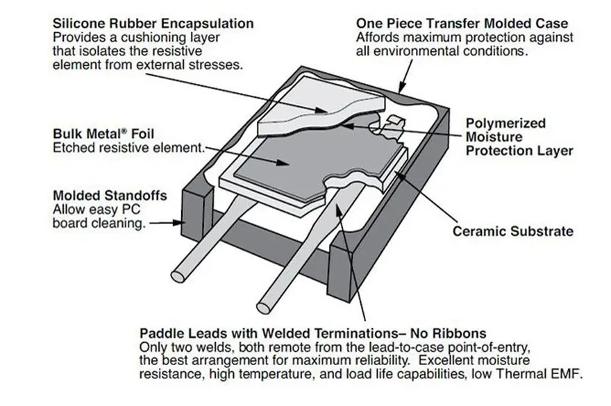
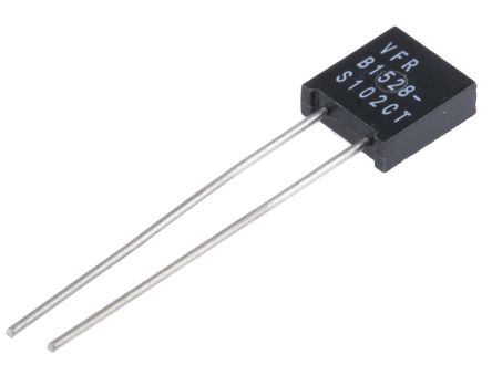
Bulk-metal-foil resistors are a distinct precision resistor technology, not simply a variant of conventional deposited metal-film resistors. A resistive metal foil is bonded to a stable substrate and photo-etched into a controlled pattern. The foil geometry and substrate system are engineered to minimise resistance change caused by temperature, mechanical strain, load, and time.
Construction
- A precision metal-alloy foil is bonded to a ceramic or glass-ceramic substrate.
- Photo-etching forms a meander pattern, while trimming establishes the final resistance value and tolerance.
- Compensation patterns are designed to reduce temperature-related strain effects and improve TCR, PCR, and long-term stability.
- Products are available as through-hole resistors, SMD resistors, resistor networks, matched sets, and selected higher-power constructions.
Performance characteristics
- TCR: exceptionally low values are available, including single-digit ppm/°C and lower in specialised series.
- Long-term stability: excellent when used within specified power, voltage, and environmental limits.
- Excess noise: very low, which is valuable in low-level DC and precision analogue circuits.
- PCR and VCR: low power coefficient and voltage coefficient support accurate gain-setting, divider, and reference functions.
- Thermal behaviour: matched resistor networks can offer superior ratio tracking when elements share a common substrate and temperature environment.
Applications
- Precision instrumentation, metrology, calibration, bridge circuits, and transducer signal conditioning.
- ADC/DAC reference and gain-setting networks, precision amplifier feedback paths, and stable voltage-divider networks.
- High-reliability equipment where accuracy over temperature, load, and time is a primary design requirement.
Limitations
- Higher cost than conventional film or metal-element resistors.
- Power and pulse capability are usually modest relative to dedicated power, shunt, or anti-surge resistor families.
- Exceptional component specifications do not eliminate system-level errors from PCB leakage, thermal gradients, connector EMF, amplifier offset, or reference-voltage drift.
For a fuller explanation of TCR and its role in precision-resistor selection, see understanding resistor temperature coefficient of resistance.
Reference Table: Key Characteristics and Typical Applications
The table below summarizes the main characteristics and typical uses of the resistor technologies discussed in this article.
Technology selection matrix
The table is an orientation tool, not a substitute for part-series data. “Pulse capability” and “voltage class” must always be verified against the data sheet, including test waveform, duration, repetition rate, resistance value, package, and mounting condition.
| Technology | Primary strength | Typical resistance domain | Precision and stability | Pulse / voltage suitability | Main design caution | Typical applications |
|---|---|---|---|---|---|---|
| Metal element | High-current and low-ohmic operation | Sub-milliohm to low-ohm | Good to very good, series dependent | Often strong for power and overload; short-pulse performance is series specific | Kelvin layout, self-heating, copper resistance, thermoelectric EMF, and parasitic inductance | Current sensing, motor drives, BMS, DC/DC converters, braking, loads, pre-charge circuits |
| Metal oxide film | Robust inorganic film for voltage and overload duty | Ohms to high resistance values | Moderate | Often good for mains, surge, and high-voltage duty; validate pulse curves | Do not equate overload rating with short-pulse survival | Bleeders, droppers, snubbers, HV dividers, industrial power supplies |
| Metal glaze / cermet | Stable fired resistive system and application-specific designs | Broad, series dependent | Moderate to good | Can be robust, depending on geometry and package | Performance varies widely; do not merge all glaze systems with oxide-film characteristics | High-voltage, power, industrial, and specialised resistor networks |
| Carbon film | Economical general-purpose resistor | Broad, series dependent | Moderate | Selected constructions can be pulse capable; generalisation is unsafe | Negative TCR, excess noise, drift, and spiral-induced inductance | General electronics, selected protection and pulse functions, specialised high-resistance parts |
| Carbon composition | Legacy behaviour and relatively low inductance | Broad legacy range | Low | Only for verified, specialised pulse or legacy use | Ageing, humidity sensitivity, high noise, non-linear behaviour, and uncertain overload response | Restoration, legacy-qualified circuits, specialised tested pulse applications |
| Conductive plastic | Long-life moving-contact resistive track | Variable-resistor track, not a mainstream fixed resistor | Good in controlled applications | Not a discrete surge-resistor technology | Wiper interface, environmental conditions, track loading, and mechanical life | Potentiometers, servo feedback, position sensors, adjustment controls |
| Bulk metal foil | Exceptional accuracy, stability, and low excess noise | Ohms to hundreds of kilohms, series dependent | Excellent | Usually not selected for high-energy pulse duty | Cost, modest power capability, and system-level thermal/leakage errors | Metrology, precision analogue, bridges, feedback networks, references, matched dividers |
Conclusion
These resistor technologies are best selected by electrical stress and required accuracy rather than by material name alone. Metal-element resistors dominate low-ohmic and high-current functions; metal-oxide and metal-glaze systems are important for voltage, surge, and robust power applications; carbon-film and carbon-composition types are now mainly application-specific or legacy choices; conductive plastic belongs primarily to variable-resistor and sensor tracks; and bulk-metal-foil technology remains the reference option for demanding precision analogue circuits.
For any new design, verify continuous power derating, working voltage, overload voltage, pulse waveform, temperature range, resistance change limits, environmental qualification, and PCB layout using the exact manufacturer data sheet. Where the resistor measures current, PCB copper and Kelvin sensing are often as important as the component itself.
Further reading
- How to choose a current-sense resistor
- Resistor fundamentals: ratings, construction, and basic parameters
- Resistivity, thermal resistance, and temperature coefficient in resistors
- Wirewound resistor construction and pulse-load behaviour
- Resistor pulse-load, power, and voltage derating guide
- High-voltage resistor selection guide
- Resistor technology selection and benchmark guidelines
FAQ: Carbon, Metal Element, Metal Oxide, Metal Foil and Conductive Plastic Resistors
Metal-element shunt resistors are normally the first choice for low-ohmic current sensing because they combine low resistance, high current capability, and useful thermal robustness. For accurate measurements, also evaluate TCR, power coefficient, thermoelectric EMF, package inductance, and Kelvin PCB routing.
Many metal-oxide resistor series are designed for overload, surge, and high-voltage duty. However, suitability depends on the exact pulse waveform, duration, repetition rate, voltage, resistance value, and permitted post-test resistance change; use the manufacturer’s pulse-load data rather than a generic technology assumption.
ower rating generally describes permitted continuous dissipation under specified thermal conditions. A pulse creates a local, time-dependent hot spot, so pulse energy, pulse width, waveform, repetition rate, working voltage, and cooling time must be checked separately.
They can offer low inductance, but low inductance does not automatically mean high pulse-energy capability. Their granular internal current paths can be damaged by surge current, so they should be used in new designs only when a particular series is verified for the actual application stress.
Conventional metal-film resistors use a deposited resistive film. Bulk-metal-foil resistors use a bonded and photo-etched foil element whose geometry and substrate are engineered for exceptionally low TCR, low excess noise, low power coefficient, and long-term stability.
Conductive plastic is mainly used for potentiometer tracks, servo feedback, and position sensors where low wear, long life, and controlled wiper noise are important. It is not normally selected as a discrete fixed resistor or a high-energy surge resistor.
Check continuous and transient voltage per resistor, voltage coefficient, divider-ratio drift, element voltage gradient, creepage and clearance, surface leakage, humidity, contamination, mounting geometry, and the effect of unequal voltage sharing across the series chain.
Bulk-metal-foil resistors are often preferred where low TCR, low drift, low excess noise, low PCR/VCR, and excellent ratio tracking are required. High-quality metal-film resistors may be more economical when the accuracy budget is less demanding.
How to select the right resistor technology
- Define the stress conditions:
set the required resistance, continuous power, maximum working voltage, overload or surge voltage, pulse waveform, pulse duration, repetition rate, and operating temperature range.
- Screen out unsuitable technologies:
remove resistor types that cannot meet the required resistance range, power density, voltage class, pulse duty, or frequency behaviour.
- Check accuracy requirements:
compare tolerance, TCR, PCR, VCR, long-term drift, excess noise, and thermoelectric EMF against the circuit error budget.
- Review mechanical and layout constraints:
confirm package size, creepage and clearance, Kelvin sensing, heat spreading, parasitic inductance, and environmental sealing.</li> <li><strong>Qualify the exact resistor series:</strong> use the manufacturer’s derating, overload, pulse-load, humidity, temperature-cycling, and endurance data before final release.
References
- Understanding resistor temperature coefficient of resistance
- Resistor pulse-load, power, and voltage derating guide
- Current-sense shunt resistor design guide
- Resistor fundamentals: ratings, construction, and basic parameters
- Resistivity, thermal resistance, and temperature coefficient in resistors
- Guide to potentiometers, rheostats, trimmers, and encoders
- How to choose a current-sense resistor
- High-voltage resistor selection guide
- Resistor technology selection and benchmark guidelines